Circuit Theory 1 · Thevenin and Norton
#26 Thevenin and Norton #26 — dependent source, short circuit, and test source
Keeps the dependent source active and finds the Thevenin resistance by both short-circuit current and a 1 A test source.
Question
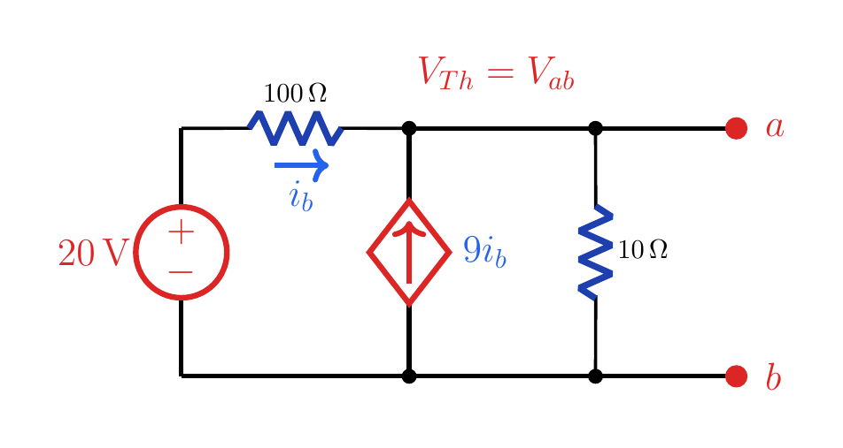
For the circuit with a 20 V independent source, current i_b in a 100 Ω resistor, a 9i_b dependent current source, and a 10 Ω branch at terminals a-b, find the Thevenin and Norton equivalents by two methods.
Written solution and narration transcript(shows the full solution)
Below are all the lines written in the notebook together with the full narration transcript.
1. Problem
The open-circuit voltage and equivalent resistance seen at a-b will be found. Thevenin with a dependent sourceIndependent source: 20 VControlling current: ibDependent source: 9ibTerminals: a-bRequired: VTh and RThKeep the dependent source activeNarration transcript
This lesson continues Thevenin equivalents, but now the circuit contains both an independent source and a dependent source. That changes the way we find R Thevenin. We cannot simply turn everything off and combine resistors, because the dependent source must stay active. The network has a 20 volt source, a 100 ohm resistor with current i b, a dependent current source equal to 9 i b, and a 10 ohm branch at terminals a and b.
2. Open-circuit voltage
The open-circuit voltage and equivalent resistance seen at a-b will be found. Open-circuit voltageNarration transcript
First find the open-circuit voltage V Thevenin. Let the terminal voltage be V Thevenin, from a to b. The current i b through the 100 ohm resistor is 20 minus V Thevenin, divided by 100. KCL at the top node gives V Thevenin minus 20 over 100, plus V Thevenin over 10, minus 9 i b equals zero. Substituting i b and simplifying gives 20 V Thevenin equals 200, so V Thevenin is 10 volts.
3. Short-circuit setup
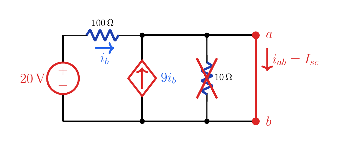
i_b=0.2 A, 9i_b=1.8 A, and I_sc=2 A. Method 1: short a-bKeep the 20 V source activeNo current in the 10 Ω branchBoth currents enter the top nodeNarration transcript
The first resistance method is the short-circuit current method. We keep the independent 20 volt source alive and short terminals a and b. The short forces the terminal voltage to zero, so the 10 ohm branch has no voltage across it. The 100 ohm resistor now carries i b equal to 20 over 100, which is 0.2 ampere. The dependent source injects 9 times that current, or 1.8 amperes, upward into the top node.
4. Short-circuit result
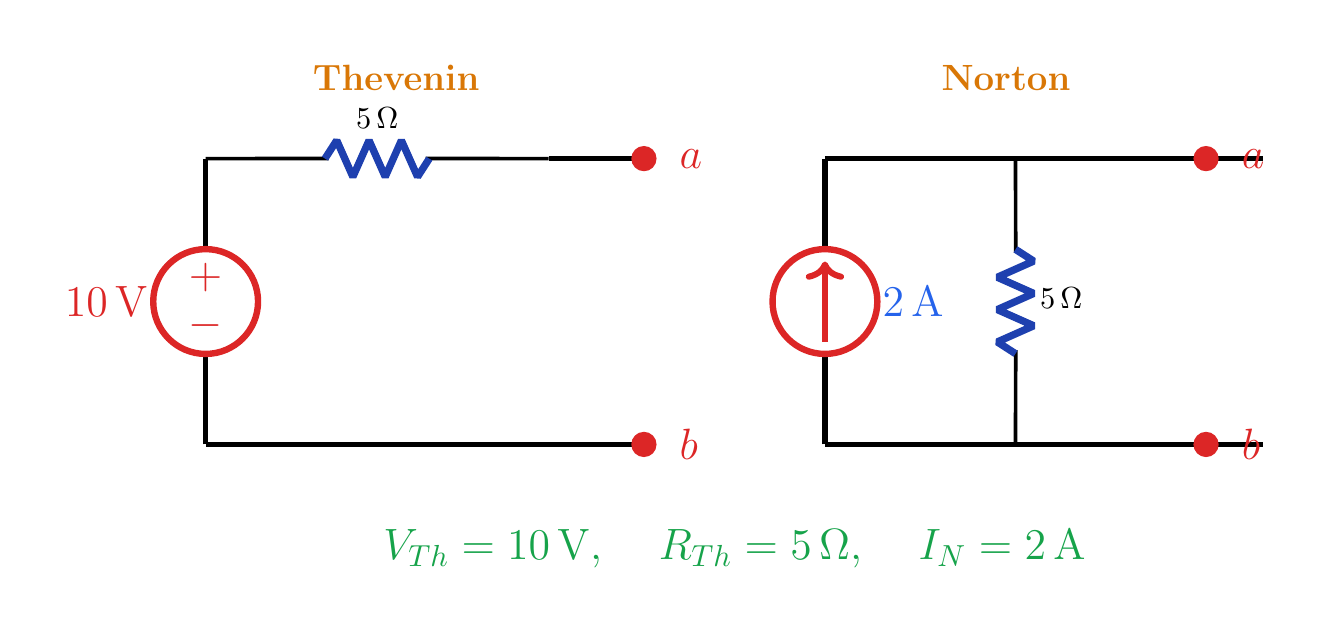
Both methods give the same terminal behavior and the same 5 Ω resistance. Short-circuit resultThevenin: 10 V in series with 5 ΩNarration transcript
The current through the short is the sum of the current coming through the 100 ohm resistor and the current injected by the dependent source. That is 0.2 plus 1.8, equal to 2 amperes. Therefore R Thevenin is V Thevenin divided by the short-circuit current. Ten volts divided by 2 amperes gives 5 ohms. The Thevenin equivalent is a 10 volt source in series with 5 ohms.
5. Test-source setup
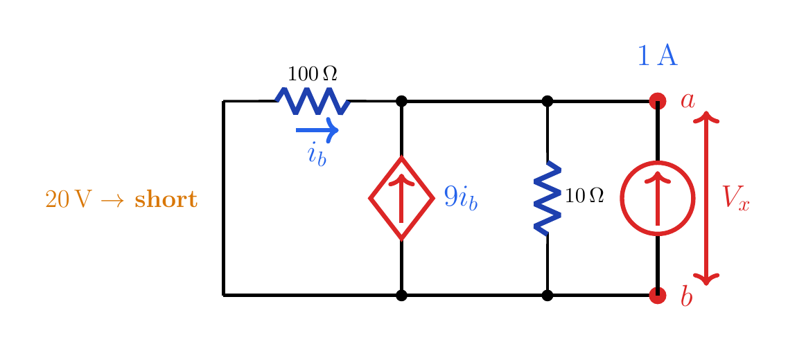
The dependent source stays active; V_x=5 V gives R_Th=5 Ω. Method 2: 1 A test source20 V → short circuitKeep the dependent source activeIt=1 A from b→aTerminal voltage: VxNarration transcript
The second method is the 1 amp test-current method. This time we turn off the independent 20 volt source, so it becomes a short circuit. Then we connect a 1 amp current source from b to a and call the resulting terminal voltage V x. Now i b is zero minus V x over 100, so i b equals negative V x over 100. KCL gives V x over 100 plus V x over 10 minus 9 i b minus 1 equals zero.
6. Test-source result
Both methods give the same terminal behavior and the same 5 Ω resistance. Test-source resultNarration transcript
Substitute i b equals negative V x over 100 into the test-source equation. The dependent-source term becomes plus 9 V x over 100, so the total is 20 V x over 100 equals 1. Therefore V x is 5 volts. Since the test current is 1 ampere, R Thevenin equals V x over 1 ampere, which is again 5 ohms. The Norton current is V Thevenin over R Thevenin, equal to 10 over 5, or 2 amperes.
7. Equivalents
Both methods give the same terminal behavior and the same 5 Ω resistance. Equivalent circuitsThevenin: 10 V in series with 5 ΩNorton: 2 A in parallel with 5 ΩNarration transcript
The main lesson is this: independent sources may be turned off when using a test source, but dependent sources stay active. For this circuit, both valid approaches agree. The open-circuit terminal voltage is 10 volts. The short-circuit current is 2 amperes, and the 1 amp test source gives V x equal to 5 volts. So the final result is R Thevenin equal to 5 ohms, with a 10 volt Thevenin source, or equivalently a 2 amp Norton source.
8. Key rule
The dependent source stays active; V_x=5 V gives R_Th=5 Ω. Invariant ruleIndependent V=0 → wireIndependent I=0 → open circuitNever turn off a dependent sourceKeep the controlling variableHere the control is ibBoth methods must give the same RThNarration transcript
One last way to remember the rule: independent sources are physical sources whose value is fixed from outside the circuit. When we use a test source method, a voltage source with zero volts becomes a wire, and a current source with zero amps becomes an open circuit. A dependent source is different. Its value is controlled by another circuit variable, like i b in this example. So it must remain in the circuit, and the controlling variable must be written into the equations.
Source video: Circuit Theory #26 | Thevenin with Dependent Sources - Short-Circuit and Test Source Methods (4:40)