Circuit Theory 1 · Thevenin and Norton
#29 Thevenin and Norton #29 — Dependent sources only
Uses a 1 A test source to find R_Th in two networks that contain dependent sources only.
Question
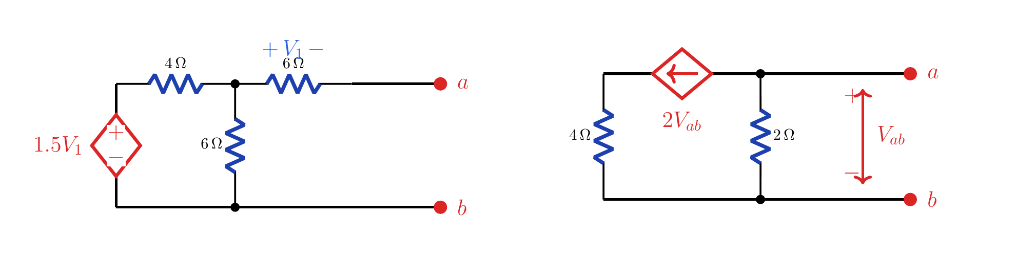
Apply a 1 A test source to two a-b port networks containing dependent sources only; find each R_Th and explain V_Th.
Written solution and narration transcript(shows the full solution)
Below are all the lines written in the notebook together with the full narration transcript.
1. Why a test source?
Example 1 uses a dependent voltage source; example 2 uses a dependent current source. Why a test source?Dependent sources onlyNo independent excitationIt=1 A, direction b→aNarration transcript
Here the circuit contains only dependent sources. That changes the question. There is no independent source that can create a definite open circuit voltage by itself, so we do not start by hunting for V Thevenin. Instead, we measure the resistance seen from terminals a and b. The clean way is to attach a test source at the port. In these two examples we will inject 1 ampere from b to a, compute the resulting terminal voltage, and then use R Thevenin equals V test divided by I test.
2. Example 1 — circuit
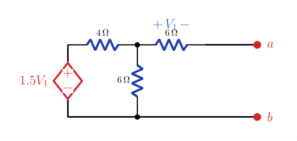
V_1 is measured across the right 6 Ω resistor from the middle node toward terminal a. Example 1 — circuitDependent voltage source: 1.5V1Resistors: 4 Ω, 6 Ω, 6 ΩV1: + at middle node, − at aTest source: 1 ADirection: b→aPort voltage: VyNarration transcript
Example one has a dependent voltage source equal to 1.5 V 1. The voltage V 1 is across the right 6 ohm resistor, with plus on the left and minus on the terminal a side. The port is still a and b. Since the network has no independent source, the target is only R Thevenin seen at a b. We connect a 1 ampere test source upward, from b to a, and call the port voltage V y.
3. Example 1 — variables
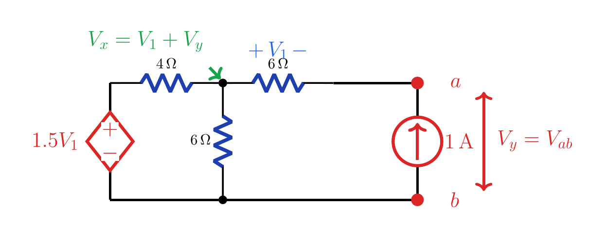
V_x=V_1+V_y and V_y=3 V, so R_Th=3 Ω. Example 1 — variablesMiddle node: VxPort node:Left node: 1.5V1Dependent source stays activeNarration transcript
Now slow down and define the node voltages. Let the middle top node be V x. Because the 6 ohm resistor on the right has voltage V 1 from left to right, and the port node is V y, we have V 1 equals V x minus V y. The same statement can be written as V x equals V 1 plus V y. That substitution keeps the dependent source and every resistor current consistent.
4. Example 1 — solution
V_x=V_1+V_y and V_y=3 V, so R_Th=3 Ω. Example 1 — solutionNarration transcript
Write KCL at the middle top node first. The current through 4 ohms is V x minus 1.5 V 1, all over 4. The current down through the middle 6 ohms is V x over 6. The current through the right 6 ohms is V x minus V y over 6, which is V 1 over 6. Substitute V x equals V 1 plus V y. After multiplying by 12, the equation becomes 5 V y plus 2.5 V 1 equals zero, so V y equals negative one half V 1. Now write KCL at terminal a. Current from a back through the right 6 ohm resistor is V y minus V x over 6, and the 1 amp test current enters the node, so V y minus V x over 6 minus 1 equals zero. That gives V 1 equal to negative 6 volts. Therefore V y is 3 volts. Since the test current is 1 ampere, R Thevenin is 3 ohms.
5. Example 2 — circuit
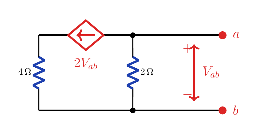
V_{ab} is the voltage of terminal a relative to b. Example 2 — circuitDependent current source: 2VabArrow points left from node aPort branch: 2 ΩReturn branch: 4 ΩIt=1 A, direction b→aNarration transcript
Example two looks different, but the idea is the same. The dependent source is now a current source of value 2 V a b, and its arrow points to the left. The port voltage V a b is positive at a and negative at b. Again, there is no independent source, so we attach the same 1 ampere test source from b to a and solve for the voltage that appears at the port.
6. Example 2 — solution
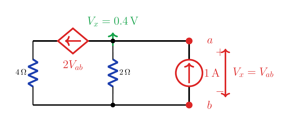
KCL gives V_x=0.4 V and R_Th=0.4 Ω. Example 2 — solutionKCL at node aNarration transcript
Use the top right node, which is terminal a. Let V x equal V a b. Current down through the 2 ohm resistor is V x over 2. The dependent current source sends 2 V a b away from this node toward the left. The 1 ampere test source enters the node. KCL is therefore V x over 2 plus 2 V a b minus 1 equals zero. Since V x is the same as V a b, we have V x over 2 plus 2 V x equals 1. That is 2.5 V x equals 1, so V x equals 0.4 volts. With a 1 ampere test current, R Thevenin is 0.4 ohms.
7. Method summary
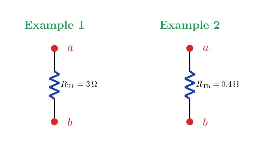
Both networks have V_Th=0 V and use a test source to measure R_Th. Method summarySource-free linear network:Keep dependent sources activeAttach a test source at the portExample 1: 3 ΩExample 2: 0.4 ΩNarration transcript
The takeaway is simple. When a port network has dependent sources but no independent source, do not invent a Thevenin voltage. Measure the port resistance. Keep every dependent source active, apply a test source, write KCL with the source direction included, and divide the measured port voltage by the test current. In example one the resistance is 3 ohms. In example two it is 0.4 ohms.
Source video: Circuit Theory #29 | Thevenin with Dependent Sources Only - Test Source Method (4:33)