Circuit Theory 2 · Two-port networks: z and y parameters
#27 Port references, finite parameter representations, measurement conditions and reciprocity
Use explicit port references and open/short test conditions to build valid impedance and admittance matrices, with reciprocity, symmetry and loading kept distinct.
Question
Consider a linear time-invariant two-port with initially relaxed storage (or an incremental small-signal model about a stated operating point), within its linear range and with internal independent-source offsets appropriately accounted for. Port pairs satisfy the port condition: current entering one terminal of each pair returns through the other. Define V1,V2 as upper-minus-lower voltages and I1,I2 entering the upper positive-reference terminal. An output load current leaving the network is IL=−I2; neither I2 nor the voltage is forced positive. Both entering-current references create consistent equation form, not automatically a symmetric coefficient matrix. Port models may be complex functions of frequency or Laplace variable; four terminal variables do not mean four independent excitations in every representation. A finite z matrix exists only where two independently chosen port currents determine unique finite voltages. V1=z11I1+z12I2,V2=z21I1+z22I2. With I2=0 and I1 nonzero,z11=V1/I1,z21=V2/I1; with I1=0 and I2 nonzero,z12=V1/I2,z22=V2/I2. The diagonal driving-point impedances refer to the other port open, not a general loaded input impedance. An open port has zero current, not necessarily zero voltage. A finite y matrix similarly requires independent voltages determining unique finite currents: I1=y11V1+y12V2,I2=y21V1+y22V2. With V2=0 and V1 nonzero,y11=I1/V1,y21=I2/V1; with V1=0 and V2 nonzero,y12=I1/V2,y22=I2/V2. A short has zero voltage, not necessarily zero current. Diagonal y terms refer to the other port shorted. Units z are ohms and y siemens, including off-diagonal terms. Tests are analytical/simulation definitions; do not physically short powered amplifier outputs or assume device limits are harmless. Wherever both finite matrices exist and detZ≠0,Y=Z^(-1), not elementwise1/z_ij. For a2x2 matrix,Δ=z11z22−z12z21 and Y=(1/Δ)[[z22,−z12],[−z21,z11]]. Finite singular representations can exist without an inverse: the ideal series-resistor two-port has Y=G[[1,−1],[−1,1]],detY=0, so arbitrary independent port currents cannot determine a unique common-mode voltage. Conversely two tied top terminals sharing a shunt R give Z=R[[1,1],[1,1]],detZ=0, so independent arbitrary voltages are unavailable. Do not require every circuit to support every parameter model at every frequency, nor silently divide by a singular determinant. For reciprocal networks, defined z12=z21 and y12=y21; passive alone is not a proof of reciprocity, and active alone is not a proof of nonreciprocity. An algebraic lossless nonreciprocal example Z=[[0,R],[−R,0]],realR, has instantaneous terminal power V1I1+V2I2=0 but unequal cross terms. Port interchange symmetry of the full matrix requires both matching diagonals and matching cross terms; equal diagonals alone is a weaker driving-point check. Source 'for a symmetric network' is a necessary-condition statement, not an unconditional converse. For a passive resistive T example with positive armsRa,Rb and shuntRc, Z=[[Ra+Rc,Rc],[Rc,Rb+Rc]]. It is reciprocal for unequal arms but fully port-symmetric only whenRa=Rb. For Ra2Ω,Rb3Ω,Rc5Ω, Z=[[7,5],[5,8]],Δ31Ω²,Y=(1/31)[[8,−5],[−5,7]]S. Neither diagonal Y is a simple reciprocal of the corresponding Z entry. Under finite loadZL, V2=−ZL I2 and Zin=z11−z12z21/(z22+ZL), assuming denominator and excitation are well-defined. V2/I1=z21 ZL/(z22+ZL); for the T example withRL4Ω,V2/V1=20/59, not the open-circuit ratio. Similarly Yin=y11−y12y21/(y22+YL) under valid finite loading. Ideal open/short limiting cases must respect representation existence. Interconnecting two-ports in series/parallel requires maintaining their port conditions; cascades are not ordinary products of z or y matrices. A properly signed transmission representation is normally preferable, with its own convention addressed in the next lesson. All117audio-source/438TSX/441graph lines and EN metadata read, SCENES AST only, no source generators executed. Existing final225.386667s/19,316,964bytes and10MP3+timings12sourceSHA equal readonly Hetzner; MP3/final correlations.9539–.983, offsets30–57ms. Initial cached-large and cached-small runs failed closed at reciprocity.607843<.62 due 'z twelve' versus 'Z12' token spelling, not demonstrated bad speech. Independent cached-small original MP3 and final147.41–171.41s both recognize all8correct z/y indices. Shared local aligner now normalizes only the closed English vocabulary of z/y/h indices11/12/21/22, V/I port variables1/2 and equivalent English numbers, equally for source/ASR tokens; symbol/index distinctions and confidence gate unchanged, Turkish/Arabic/default API behavior preserved. Expanded pieces retain the original whole-word time extent, not invented phoneme times. Actual independent transcript confidence rises.607843→1 with exactly the same narration and ASR timestamps. Full original cached-large alignment then passes10steps at1.0000,36cue intervals and recognized passages all reviewed. Source MP3/video/say unchanged; no per-lesson spoken/alignment override or prompt. This remains machine-assisted evidence, not complete human listening/teaching approval. All10final frames reviewed; z-measure→z-definition and y-measure→y-definition use same-final references. Original measurement diagrams' right-driven arrow points outward, contrary to entering-current convention; oversized box geometry collapses right test leads/short into the box. Their ratios are correctly rewritten with explicit test conditions, without repainting the source raster. Retained port-view voltage signs are low relative to terminals, so the explicit upper-minus-lower convention governs; current arrows are correct. Definition matrices and terms are readable; choose-model spells 'times' in a raster matrix shorthand, not a scalar or entrywise rule; full-matrix existence/inverse scope is explicit. Reciprocity lines/conditions are readable with the qualifications above; workflow and wrap clear. Eight unique original frames across10roles. Technical unpublished draft; no TTS, paid generation, model download, video render/upload, publication/access/security/egress change. Full motion and human teaching/publication QA remain outstanding.
Written solution and narration transcript(shows the full solution)
Below are all the lines written in the notebook together with the full narration transcript.
1. Replace internal detail with a valid two-port model
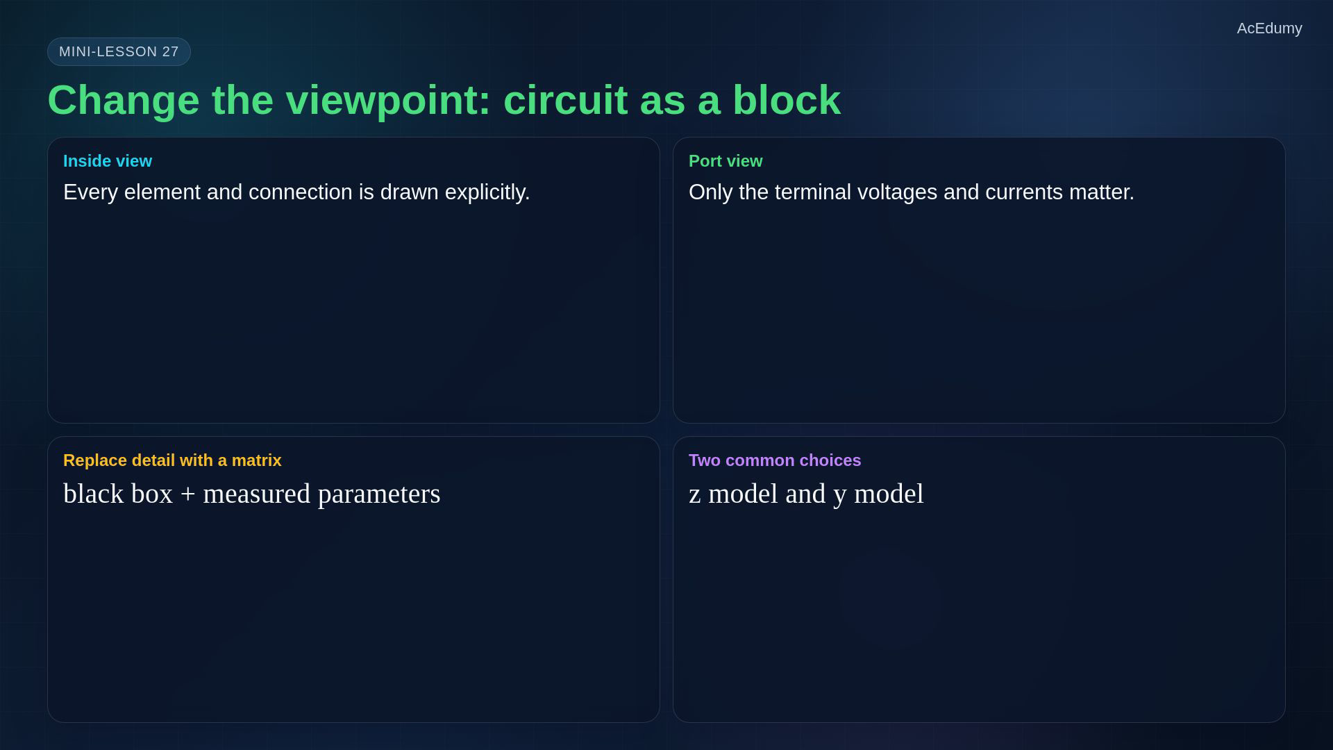
Original-video reference; two measurement-diagram roles use the corresponding definition frames. Test conditions and port-current signs are explicit in the notebook. Change from internal elements to terminal behavior.A block model must preserve the chosen port voltage and current relations.For a linear two-port in its valid operating range, two terminal pairs can be described by suitable parameter matrices.Narration transcript
So far, most circuits were drawn from the inside: every resistor, capacitor, inductor, op-amp, and connection. Now we change the viewpoint. A complicated circuit can be treated as a two-port block: one input port, one output port, and a small set of measured parameters.
2. State voltage polarity and entering-current references
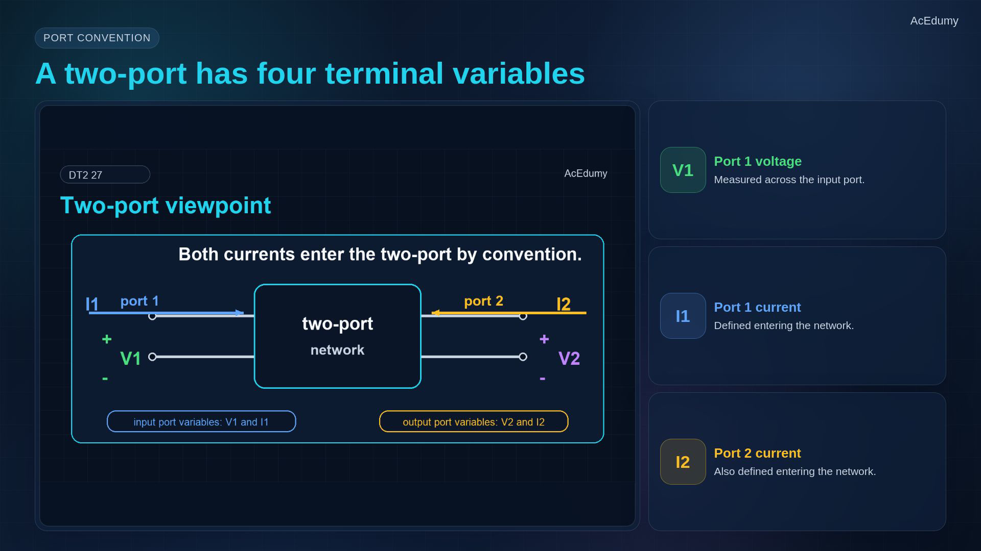
Original-video reference; two measurement-diagram roles use the corresponding definition frames. Test conditions and port-current signs are explicit in the notebook. Define each port voltage from its upper terminal to its lower terminal.Both reference currents enter the upper, positive-reference terminals and return through the paired lower terminals.The same entering-current convention gives a consistent equation form; it does not make every parameter matrix symmetric.Narration transcript
A two-port has four terminal variables: voltage and current at port one, and voltage and current at port two. The standard convention is that both currents enter the network. This may feel a little strange at the output port, but it makes the equations symmetric and reusable.
3. Predict voltages from independent port currents
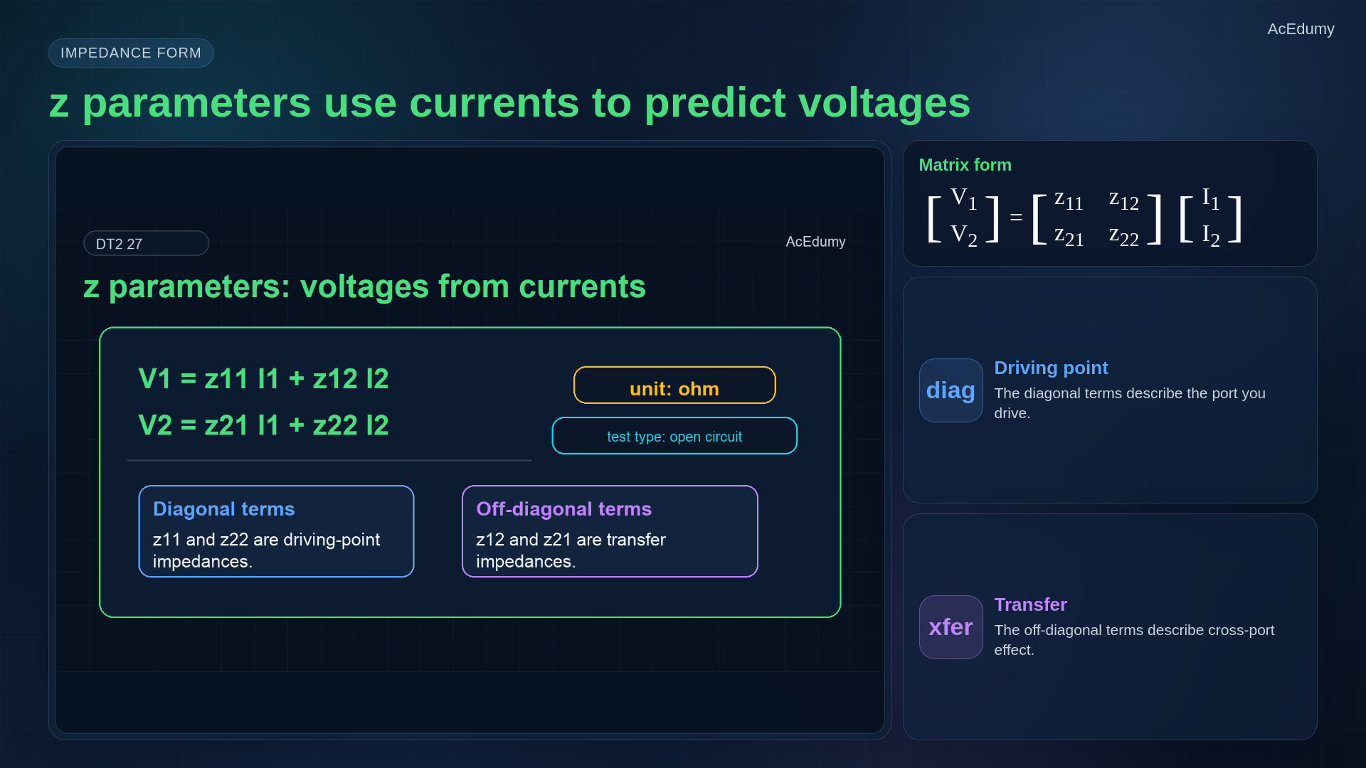
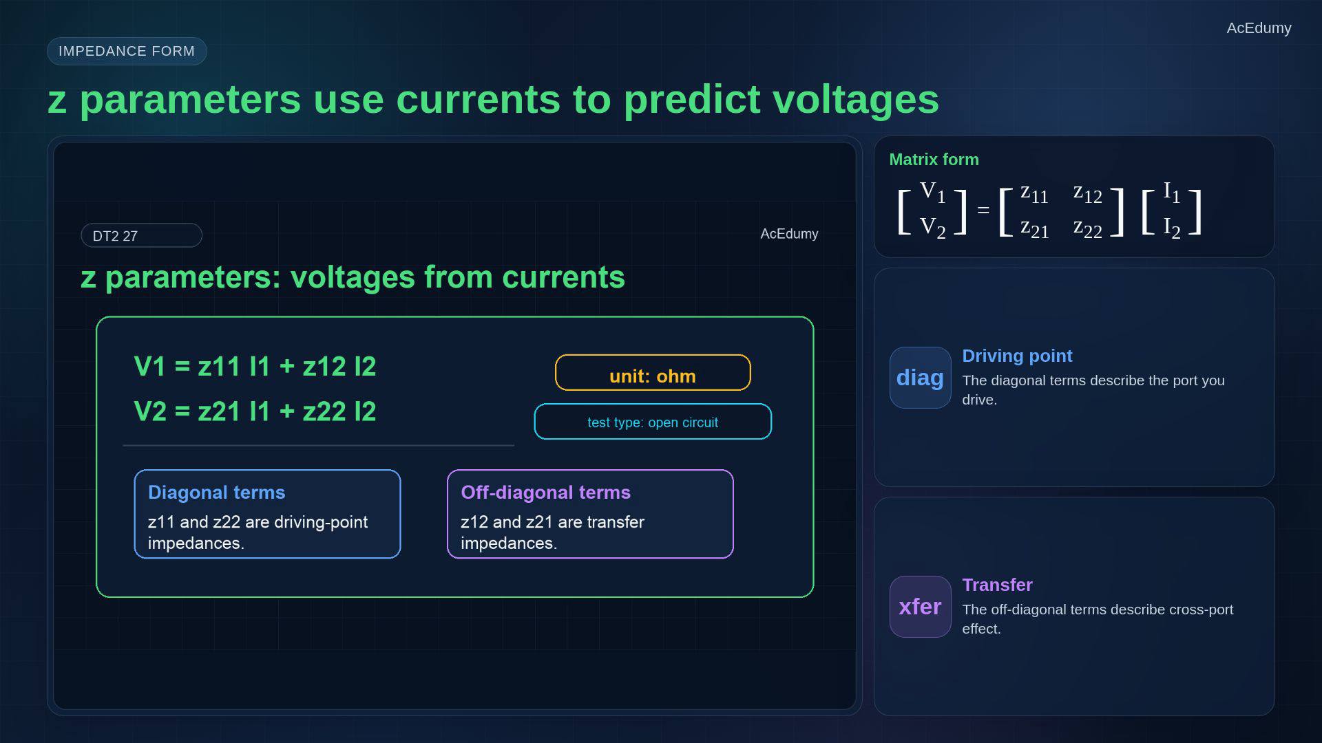
Original-video reference; two measurement-diagram roles use the corresponding definition frames. Test conditions and port-current signs are explicit in the notebook. Use an impedance matrix when independent port currents determine finite, unique port voltages.First voltage equation:Second voltage equation:The diagonal terms are open-circuit driving-point impedances; the off-diagonal terms are transfer impedances.Every impedance parameter has units of ohms; the matrix entries may be complex and frequency-dependent.Narration transcript
The first description is the z-parameter model. It writes port voltages as functions of port currents. The diagonal terms are driving-point impedances. The off-diagonal terms are transfer impedances. Every z value has the unit ohm.
4. Extract z parameters under open-circuit conditions
Original-video reference; two measurement-diagram roles use the corresponding definition frames. Test conditions and port-current signs are explicit in the notebook. Extract each impedance-matrix column with the other port open; the driven current must be nonzero.With port two open, so its current is zero:With port one open, so its current is zero:Narration transcript
To measure z parameters, use open-circuit tests. If port two is open, its current is zero, so z eleven and z twenty one come directly from voltage divided by the driven current. If port one is open, its current is zero, so z twelve and z twenty two are found the same way from the other side.
5. Predict currents from independent port voltages
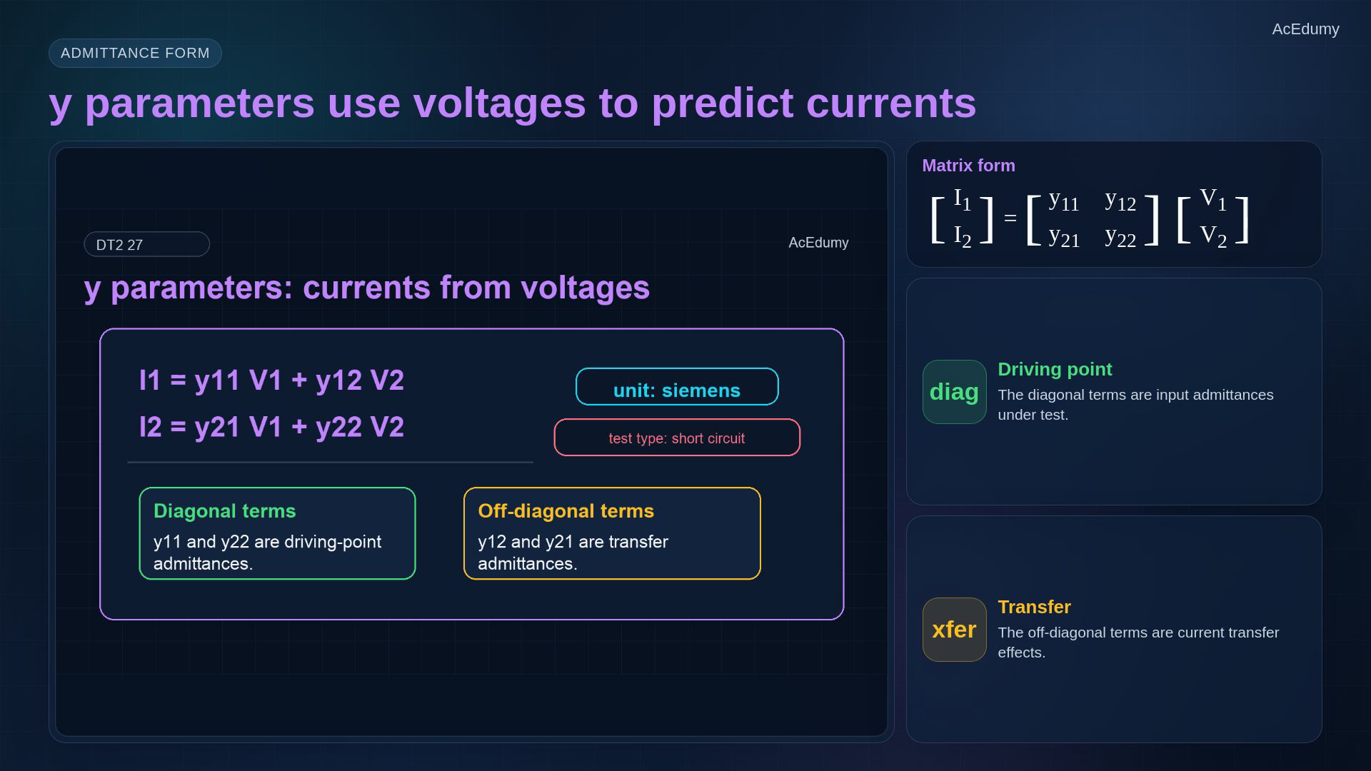
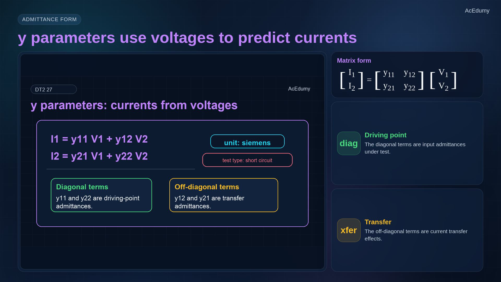
Original-video reference; two measurement-diagram roles use the corresponding definition frames. Test conditions and port-current signs are explicit in the notebook. Use an admittance matrix when independent port voltages determine finite, unique port currents.First current equation:Second current equation, with both reference currents still entering:Diagonal entries are short-circuit driving-point admittances; cross entries are transfer admittances. All have units of siemens.Narration transcript
The second description is the y-parameter model. It writes port currents as functions of port voltages. The diagonal terms are driving-point admittances, and the off-diagonal terms are transfer admittances. Every y value has the unit siemens.
6. Extract y parameters under short-circuit conditions
Original-video reference; two measurement-diagram roles use the corresponding definition frames. Test conditions and port-current signs are explicit in the notebook. Extract each admittance-matrix column with the other port shorted; the driven voltage must be nonzero.With port two shorted, so its voltage is zero:With port one shorted, so its voltage is zero:Narration transcript
To measure y parameters, use short-circuit tests. If port two is shorted, its voltage is zero, so y eleven and y twenty one are obtained by driving port one. If port one is shorted, its voltage is zero, so y twelve and y twenty two are obtained by driving port two.
7. Choose an existing finite parameter representation
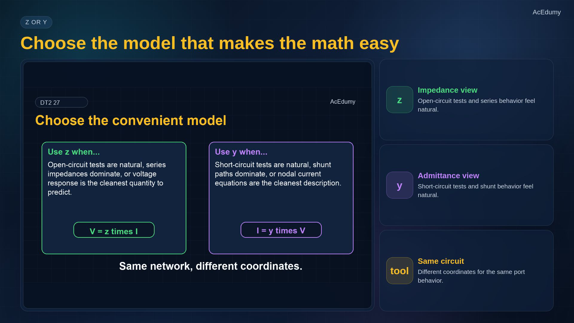
Original-video reference; two measurement-diagram roles use the corresponding definition frames. Test conditions and port-current signs are explicit in the notebook. Choose a parameter representation that exists and is convenient for the task.Impedance form is convenient for open-circuit conditions and suitable series interconnections.Admittance form is convenient for short-circuit conditions and suitable parallel or nodal descriptions.When both matrices exist and are nonsingular, conversion is a matrix inverse, not entrywise reciprocals:Narration transcript
Which model should you choose? Use z when open-circuit tests are natural, or when series behavior and impedances are easier to see. Use y when short-circuit tests are natural, or when shunt behavior and nodal equations are easier. The model is a tool, not a religion.
8. Distinguish reciprocity from port interchange symmetry
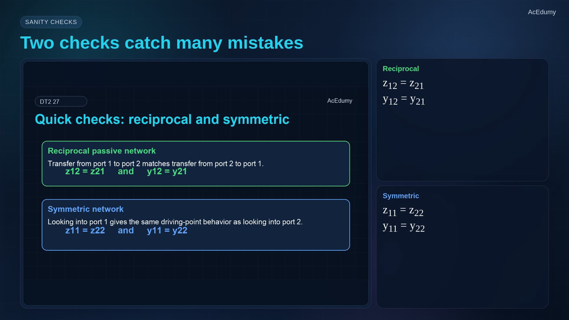
Original-video reference; two measurement-diagram roles use the corresponding definition frames. Test conditions and port-current signs are explicit in the notebook. Keep reciprocity, passivity and port-interchange symmetry distinct.For a reciprocal two-port, wherever these parameter matrices exist:Port-interchange symmetry also requires equal diagonal terms, not only those cross-term conditions:Narration transcript
Two quick checks help catch mistakes. For a reciprocal passive network, the transfer parameters match: z twelve equals z twenty one, and y twelve equals y twenty one. For a symmetric network, the two driving-point parameters match: z eleven equals z twenty two, and y eleven equals y twenty two.
9. Reuse the block with correct source and load conditions
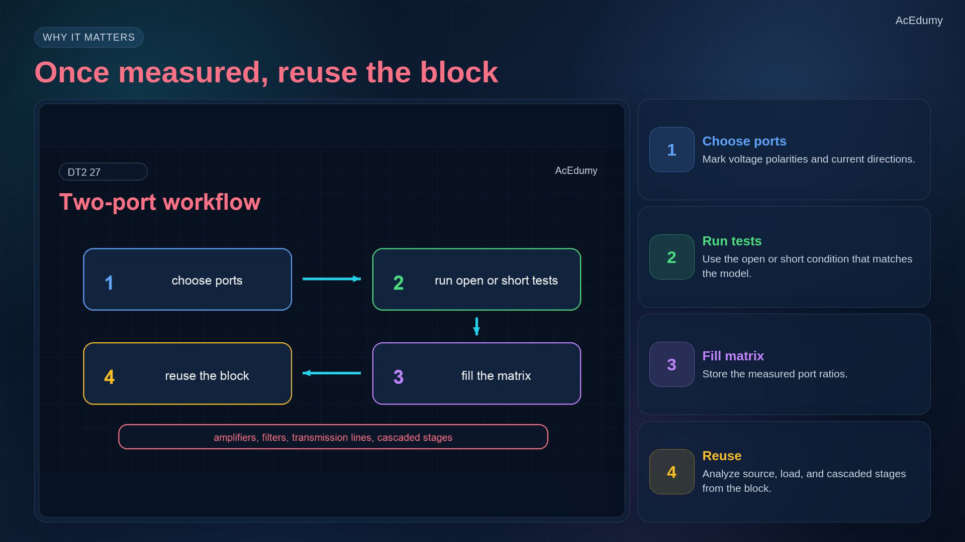
Original-video reference; two measurement-diagram roles use the corresponding definition frames. Test conditions and port-current signs are explicit in the notebook. Choose references, verify the model exists, and specify the operating frequency or transform variable.Derive or simulate the required test ratios with the right open or short condition; test definitions do not require physically shorting a powered amplifier.Use the matrix with the actual source and load; a load current leaving port two has the opposite sign:Narration transcript
The workflow is simple. Draw or simulate the circuit, choose the port convention, run the required open or short tests, fill the matrix, and then use the matrix instead of redrawing the inside every time. That is why two-port models are so useful in amplifiers, filters, transmission lines, and cascaded stages.
10. Summarize z and y models and their limitations
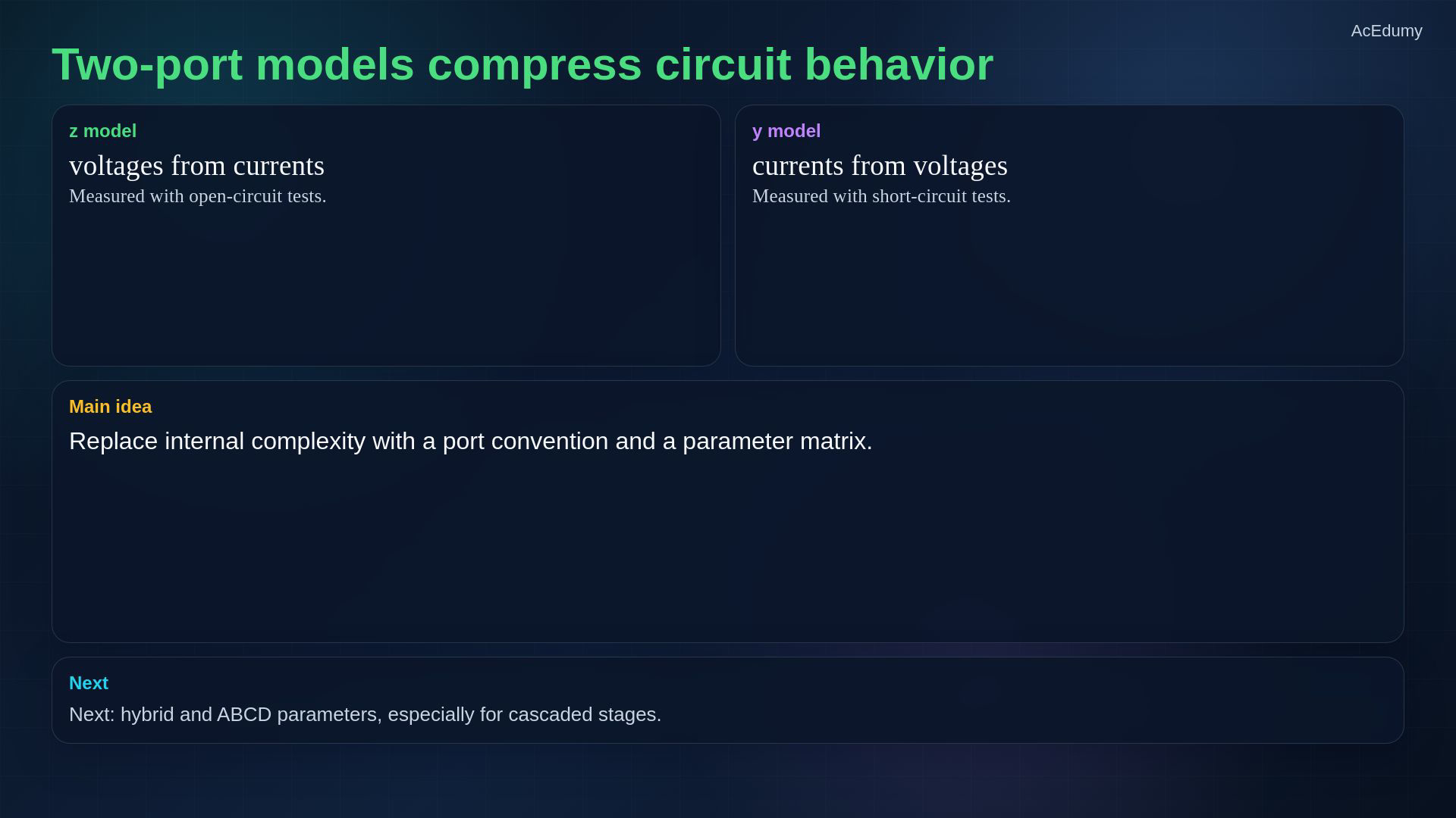
Original-video reference; two measurement-diagram roles use the corresponding definition frames. Test conditions and port-current signs are explicit in the notebook. Summary: a two-port model compresses linear terminal behavior, not every internal detail.Retain the port polarity, entering-current convention, operating conditions and model-existence assumptions.Impedance form predicts port voltages from currents using open-circuit parameter tests.Admittance form predicts port currents from voltages using short-circuit parameter tests.For cascades, a suitable transmission matrix is often more convenient; do not simply multiply z or y matrices.Narration transcript
Summary. A two-port block replaces internal complexity with port variables and a parameter matrix. z parameters use currents to predict voltages and are measured with open circuits. y parameters use voltages to predict currents and are measured with short circuits. Next, we can extend this view to hybrid and ABCD parameters, where cascaded stages become much easier.
Source video: Circuit Theory-2 #27 | Two-Port Networks: z and y Parameters (3:45)