Electronics 1 · Electronics Basics
#12 Zener diode — voltage regulator and worked example
Explain controlled reverse breakdown, then solve the conduction test, current split, and power limit for two Zener-regulator loads.
Question
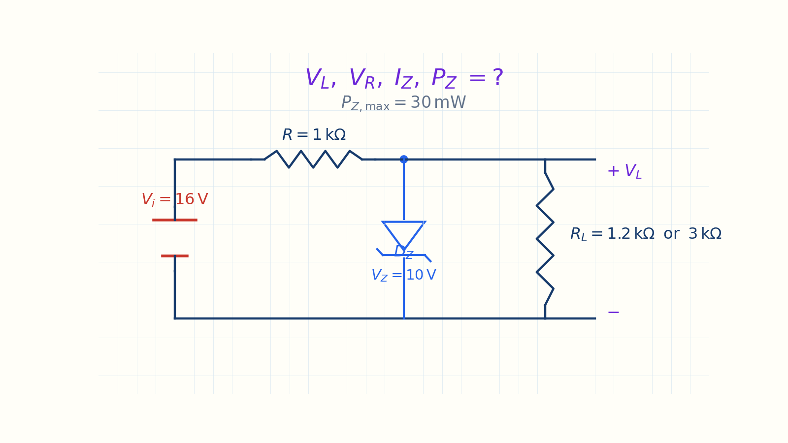
For the shunt Zener regulator with V_i = 16 V, R = 1 kΩ, V_Z = 10 V, and P_{Z,max} = 30 mW, find V_L, V_R, I_Z, and P_Z for (a) R_L = 1.2 kΩ and (b) R_L = 3 kΩ. Test whether the Zener conducts before solving each case.
Written solution and narration transcript(shows the full solution)
Below are all the lines written in the notebook together with the full narration transcript.
1. Why use a Zener?
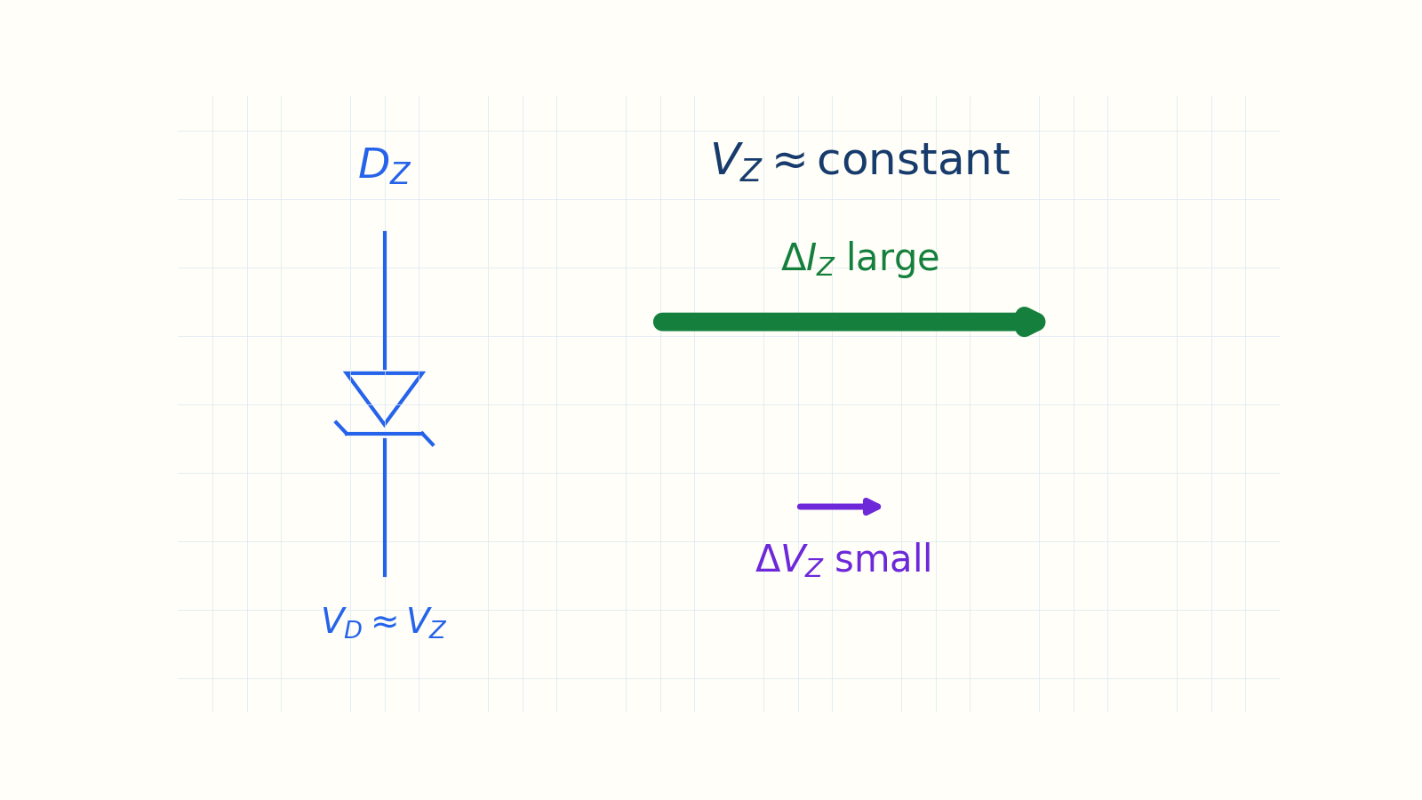
In breakdown, Zener current changes over a wide range while V_Z changes very little. Goal: a steady voltage under changing conditionsOrdinary diodes → shape and rectifyZener diode → voltage limit and referenceMechanism: controlled reverse breakdownFinish: complete analysis for two loadsNarration transcript
Welcome back. Up to now, our diodes have shaped signals. This one has a completely different job, and honestly it is one of the most useful tricks in electronics: holding a voltage perfectly steady. Picture this. Your power supply wanders. Sixteen volts now, a little more later, a little less after that. But the circuit you are feeding needs a rock-steady voltage that simply will not move. So here is the question. Can one cheap component act like a wall, so that no matter how hard you push, it refuses to let the voltage climb past a set value? Yes. It is the Zener diode. And the trick behind it is something we have always treated as a failure: reverse breakdown. Let us see why that failure is actually a gift.
2. Controlled reverse breakdown
In breakdown, Zener current changes over a wide range while V_Z changes very little. Forward: ordinary diode, ≈ 0.7 VReverse: current is initially tiny|VD| = VZ → controlled breakdownIn breakdown: large ΔIZ, small ΔVZCondition: keep IZ and PZ within ratingsNarration transcript
Let us recall how a normal diode behaves. You already know most of this. In the forward direction, it conducts after about 0.7 volts. In reverse, it blocks current, until the reverse voltage gets so large that the diode breaks down and current suddenly rushes through. In an ordinary diode, that breakdown is destructive. It kills the part. Here is the clever bit. A Zener diode is built on purpose to break down, at a precise, low reverse voltage we call the Zener voltage, V sub z, and to sit there safely, as long as we do not let too much current through. Its symbol is just a diode with a bent, Z-shaped bar on the cathode. That little Z is your reminder. And here is the one fact that makes everything work: once a Zener is in breakdown, the voltage across it stays almost constant at V sub z, no matter how much current flows. Hold onto that. It is the whole reason the Zener is useful.
3. Zener I–V characteristic
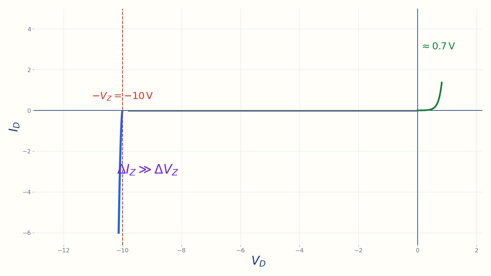
The steep region near minus V_Z enables voltage regulation. Right side: forward conduction ≈ 0.7 VLeft side: reverse blocking regionVD = −VZ → sharp kneeSteep branch → nearly constant voltageRegulation:Narration transcript
Let us actually see that, on the current-voltage curve. Current up the vertical axis, voltage across the horizontal. To the right is the forward direction. Like any diode, the Zener turns on near 0.7 volts and current shoots up. Now the interesting part. To the left, the reverse region. At first, as we go more negative, almost no current flows. The diode just blocks. But the moment we reach the Zener voltage, here, at minus ten volts, the curve bends hard and plunges almost straight down. And this is the part to really watch. Follow the operating point as the current grows. It slides far down this steep line. The current changes a lot. But look at the voltage underneath it. It barely moves. It stays pinned right around ten volts. That near-vertical wall is the entire idea: a huge range of current, but an almost fixed voltage. That is exactly what we want from a voltage reference.
4. Overflow-weir analogy
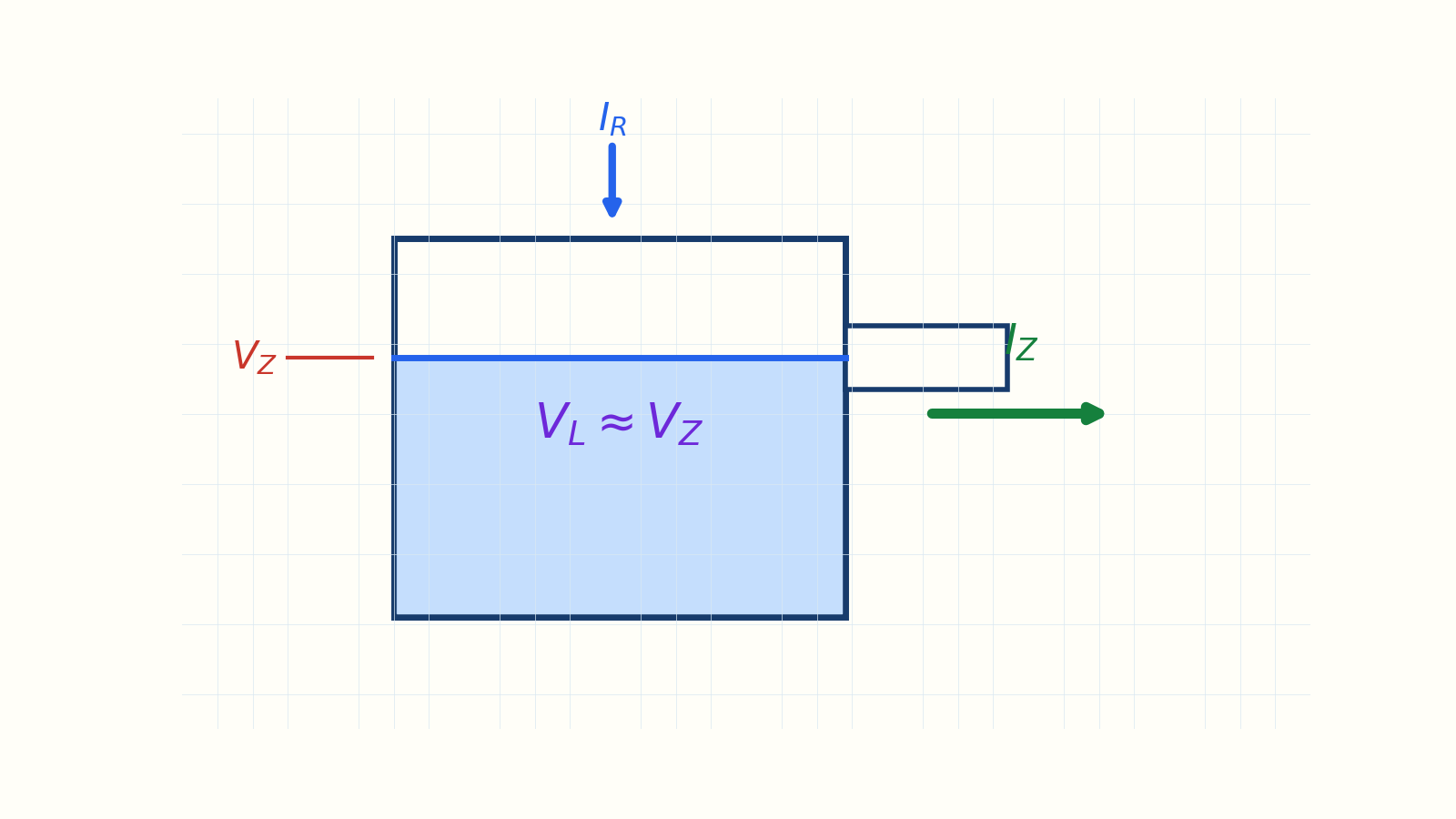
The weir height represents V_Z and the overflow represents I_Z. Water level ↔ output voltageWeir height ↔ VZLevel < VZ → Zener OFFExtra water ↔ overflow current IZFixed level ↔ regulated voltageNarration transcript
Here is a way to picture it. Think of a tank being filled with water. The water level is our voltage. On the side of the tank there is an overflow channel, a weir, at a fixed height. That height is the Zener voltage. While the level is below the weir, no water spills, and the Zener is off. But once the level reaches the weir, any extra water simply spills over and runs away. The level cannot rise past the weir, no matter how fast we pour. The spilling water is the Zener current. The fixed level is our regulated voltage. That is exactly how a Zener holds the output steady.
5. Regulator conduction test
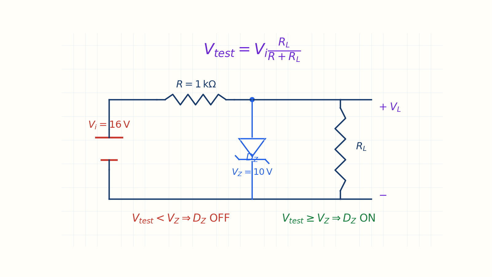
Remove the Zener mentally and compare V_test with V_Z. Circuit: series R, DZ ∥ RLTrap: do not assume VL = VZRemove Zener:Vtest < VZ → DZ OFFVtest ≥ VZ → DZ ON, VL ≈ VZRule: test first, then trustNarration transcript
Now let us build a real regulator. We place a series resistor R between the input and our output node. Across the output we connect the Zener, and in parallel with it, the load resistor R sub L. The resistor controls how much water we pour in. The Zener is the weir. Now, here is the single biggest mistake people make with Zeners. They see a Zener and assume the output is always V sub z. Do not. Sometimes the Zener is not even on. So before anything, ask one question every single time: is the Zener actually on? Here is the test. Mentally pull the Zener out, and find the open-circuit voltage at the node, using the voltage divider: V equals V sub i times R sub L, over R plus R sub L. Then compare. If that voltage is at or above V sub z, the Zener switches on, and the output locks to V sub z. But if it is below V sub z, the Zener stays off, there is no spillover, and the output just drifts with the load, unregulated. So, test first, then trust. Keep that rule, because our very first case is going to trip on it.
6. Given values and power limit
Find V_L, V_R, I_Z, and P_Z for R_L = 1.2 kΩ and 3 kΩ. PZ,max = 30 mWIZ,max = 30 mW/10 V = 3 mARL: 1.2 kΩ and 3 kΩFind: VL, VR, IZ, PZNarration transcript
Here is our circuit. The input is a fixed sixteen volts. The series resistor R is one kilo-ohm. The Zener voltage is ten volts. And its maximum power rating is thirty milliwatts. Before we touch the loads, let us pull one number out of that power rating: the most current the Zener can safely take. Power is voltage times current, so current is power divided by voltage. I sub z max equals thirty milliwatts divided by ten volts. Thirty divided by ten is three, and milliwatts over volts gives milliamps, so I sub z max is three milliamps. Keep that in your back pocket. We will check against it at the end. Now the question: find the load voltage, the resistor voltage, the Zener current, and the Zener power, for two different loads. First, a load of 1.2 kilo-ohms. Then, a load of three kilo-ohms.
7. Case A — Zener off
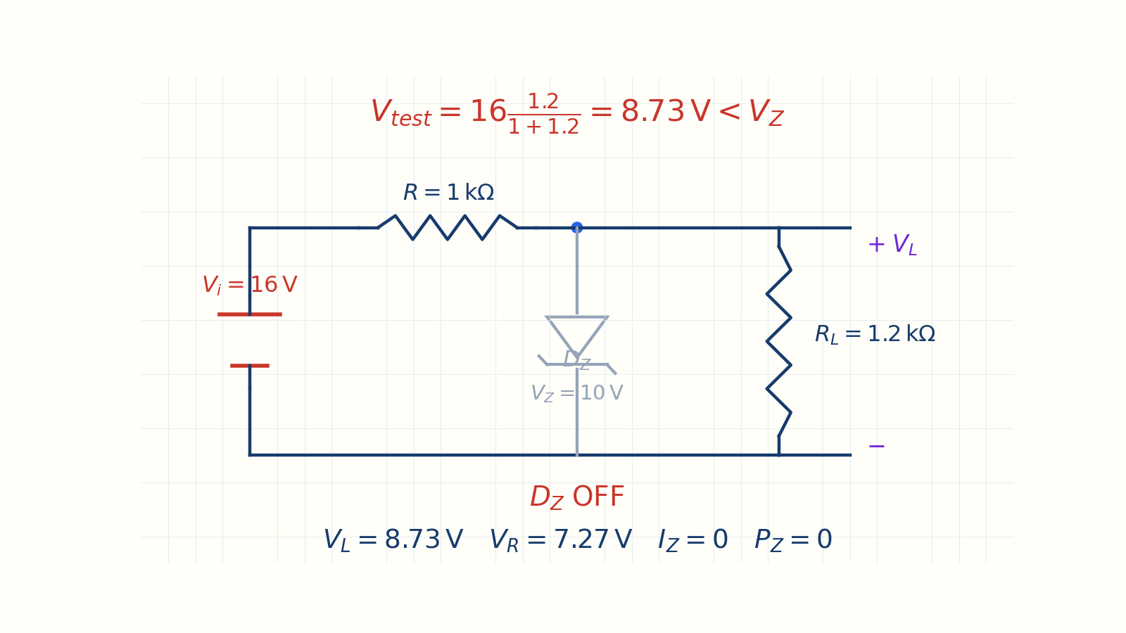
V_test = 8.73 V, so the Zener is off and the output is not regulated. 8.73 V < 10 V → DZ OFFI = 16/(1 + 1.2) kΩ = 7.27 mAHeavy load → node below 10 V, no regulationNarration transcript
Case a. The load is 1.2 kilo-ohms. Test first, like we agreed. Pull the Zener out, and find the node voltage with the divider. Let us do it piece by piece. The bottom first: one plus 1.2 is 2.2. The top: sixteen times 1.2 is 19.2. Now divide: 19.2 over 2.2 is 8.73 volts. Now the all-important compare. Is 8.73 above ten? No. It is below. So the Zener never turns on. It just sits there, off. And once the Zener is off, this is nothing but a plain series circuit: the input, R, and R sub L, all in a line. The current is the input over the total resistance: sixteen over 2.2 kilo-ohms. Watch the unit. It is kilo-ohms, so the answer lands in milliamps. Sixteen over 2.2 is 7.27 milliamps. The load voltage is that current times the load: 7.27 milliamps times 1.2 kilo-ohms. Milliamps times kilo-ohms gives volts, so that is 8.73 volts, the same node voltage, exactly as it must be. The resistor takes whatever is left: sixteen minus 8.73 is 7.27 volts. And the Zener? No current. So the Zener current is zero, and the Zener power, ten times zero, is zero. Look what happened. The load was heavy enough to pull the node below ten volts, and our regulation just vanished. This is the trap. If you had blindly written output equals ten volts, you would be wrong.
8. Case B — Zener on
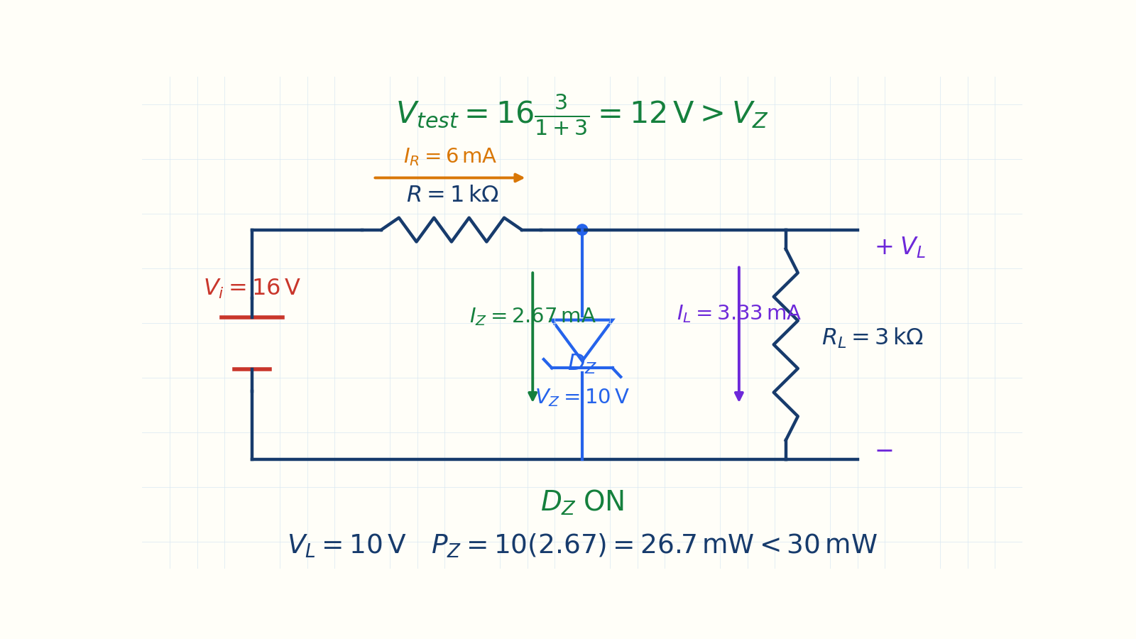
The output is 10 V, Zener current is 2.67 mA, and Zener power is 26.7 mW. 12 V > 10 V → DZ ON; VL = 10 VVR = 6 V; IR = 6 mAIL = 10/3 kΩ = 3.33 mAIZ = IR − IL = 2.67 mAPZ = 10·2.67 = 26.7 mW < 30 mWNarration transcript
Case b. Now a lighter load, three kilo-ohms. Same test. Pull the Zener. The divider gives sixteen times three over one plus three. The bottom: one plus three is four. The top: sixteen times three is forty-eight. Divide: forty-eight over four is twelve volts. Compare. Is twelve above ten? Yes. So this time the Zener switches on, and pins the output. The load voltage is ten volts, locked. The resistor takes the rest: sixteen minus ten is six volts. Now the current through R: six volts over one kilo-ohm. Kilo-ohm again, so milliamps. Six over one is six milliamps. The load pulls its own share: ten volts over three kilo-ohms is 3.33 milliamps. And the Zener mops up the difference. That is just Kirchhoff's current law at the node: current in equals current out. Six minus 3.33 is 2.67 milliamps. Notice the size. A couple of milliamps, exactly what you would expect for a small Zener. If you had gotten amps, you would know a kilo went missing. Last step, the power: V sub z times I sub z, ten volts times 2.67 milliamps, is 26.7 milliwatts. And always, always check it against the rating. 26.7 is under thirty, so the Zener is safe. The output is regulated at a clean ten volts. One caution: had that power come out above thirty milliwatts, the Zener would cook, and the fix would be a larger series resistor to throttle the current.
9. Solution algorithm
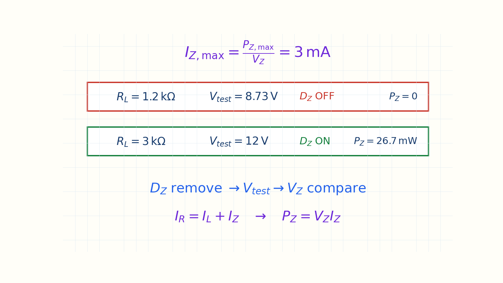
Compare V_test first, then apply KCL and the power check. 1) Remove the Zener and find Vtest2) Compare Vtest with VZ3) ON: VL ≈ VZ; OFF: divider result4) Split currents with IR = IL + IZ5) Check PZ = VZ IZ against the ratingA: no regulation; B: regulated at 10 VNarration transcript
Let us pull it together. A Zener diode is a diode built to live in reverse breakdown, where its voltage barely moves off V sub z. That makes it a voltage reference, like a weir that fixes a water level. To use one as a regulator, never skip the test: pull the Zener, find the divider voltage, and compare it to V sub z. We saw both outcomes. The heavy 1.2 kilo-ohm load left the Zener off, and regulation collapsed. The lighter three kilo-ohm load switched it on, locking the output at ten volts, safely under its power limit. One line to remember: test first, then trust. Next time, we make life harder. We design a regulator that has to hold steady while both the load and the input voltage change.
Source video: Electronics Basics #12 | Zener Diode: The Voltage Regulator (Intro + Worked Example) (10:41)