Electronics 1 · Electronics Basics
#13 Zener regulator — the safe operating window
Build the safe operating window of a Zener regulator from the two boundary calculations for variable load and variable input.
Question
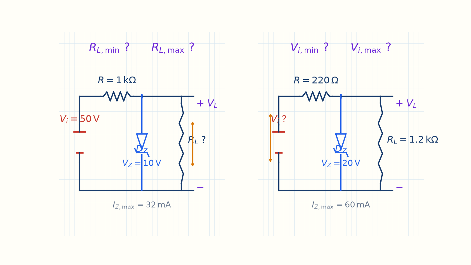
(A) For V_i = 50 V, R = 1 kΩ, V_Z = 10 V, and I_{Z,max} = 32 mA, find the R_L range that preserves regulation. (B) For R = 220 Ω, V_Z = 20 V, I_{Z,max} = 60 mA, and R_L = 1.2 kΩ, find the input-voltage range that preserves regulation.
Written solution and narration transcript(shows the full solution)
Below are all the lines written in the notebook together with the full narration transcript.
1. Why a window?
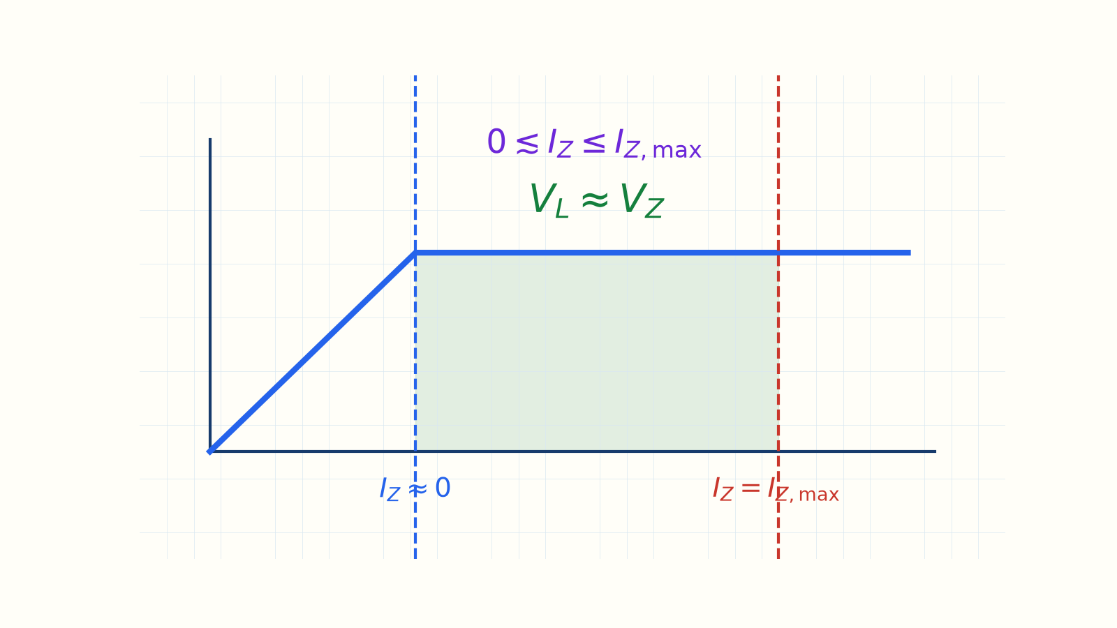
I_Z is nearly zero at the lower edge and maximum at the upper edge. Real circuits have changing Vi and RLOne direction → Zener turns offThe other direction → power limit exceededGoal: locate both safe edgesOutput is fixed only inside the windowNarration transcript
Welcome back. Last time we ran the one test that tells you whether a Zener is even on, and pinned a single load and input to one answer. But real life is messier: your supply voltage drifts, and your load changes as devices switch on and off. So here is the real question: between what limits does the Zener keep regulating? Push too far one way and regulation collapses; push too far the other way and the Zener burns. Today we find that safe window twice: once for a changing load, once for a changing input.
2. The two edges
I_Z is nearly zero at the lower edge and maximum at the upper edge. Lower edge:Below it: VL < VZ, Zener OFFUpper edge:Above it: excessive Zener powerBetween them:Narration transcript
Every Zener regulator lives between two limits. The lower limit is the moment the Zener just barely turns on, its current dropped to almost zero. Go below that, too heavy a load or too low an input, and the node falls under V sub z, so the Zener shuts off and the output is no longer fixed. The upper limit is the Zener's power: its current must never exceed I sub z max. Go above that, too light a load or too high an input, and the Zener overheats. Between these two edges, the output sits flat at V sub z. Picture the output as a function of the input: a flat plateau at V sub z, with a cliff on the low side and a burnout on the high side. Our whole job is to find where that plateau begins and ends.
3. A — fixed input
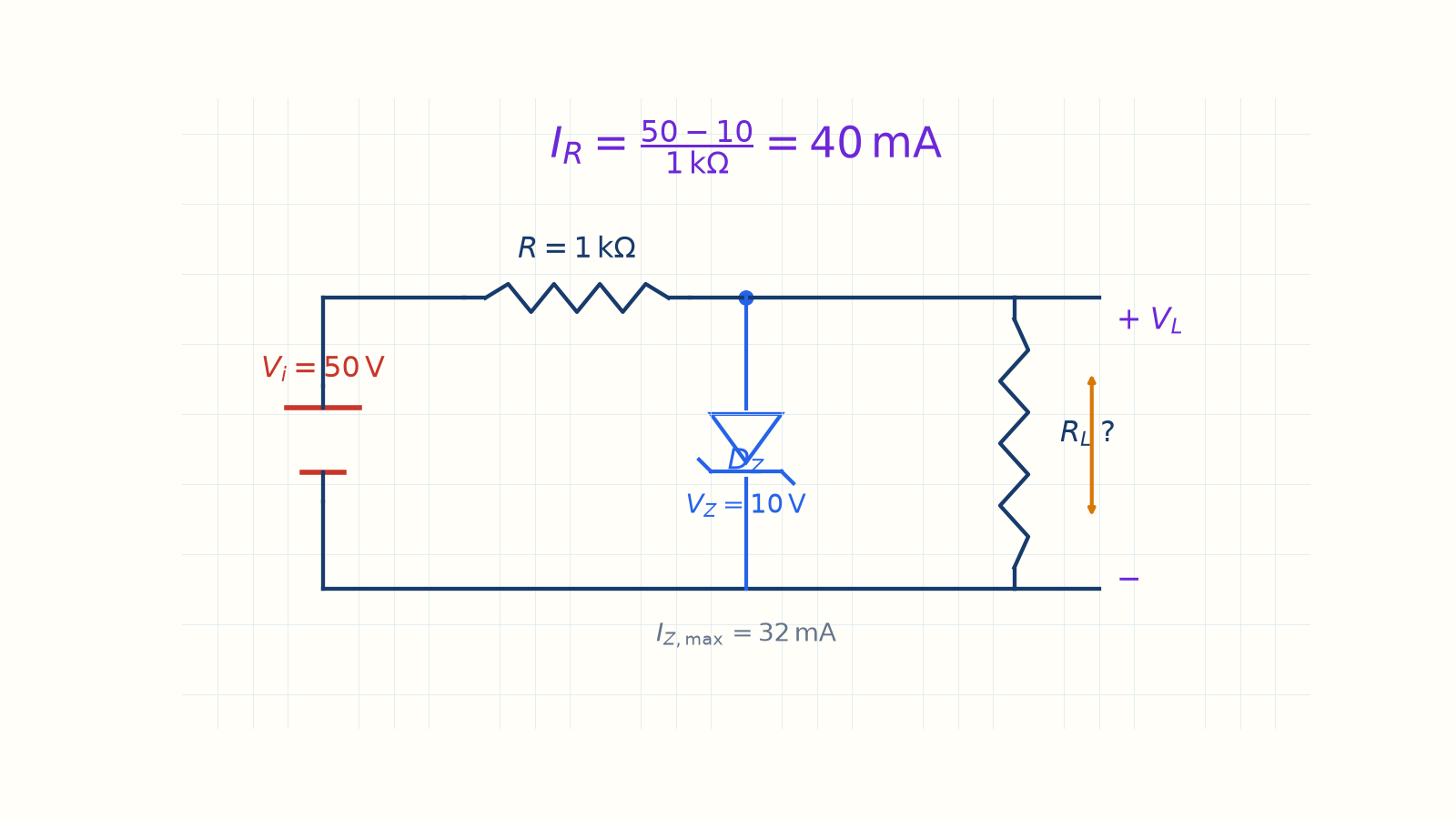
The series current remains fixed at 40 mA while the Zener regulates. VZ = 10 V; IZ,max = 32 mARL is variableIR = 40 V/1 kΩ = 40 mANarration transcript
First case. The input is fixed at fifty volts, the series resistor is one kilo-ohm, the Zener is ten volts, and its maximum current is thirty-two milliamps. The load R sub L is what changes. Here is the insight that makes this easy. As long as the Zener is on, the output is pinned at ten volts, so the resistor always drops fifty minus ten, which is forty volts. Forty volts over one kilo-ohm is forty milliamps. So the series current is fixed at forty milliamps. That forty milliamps splits between the Zener and the load, and that split is the whole story.
4. A — heaviest load
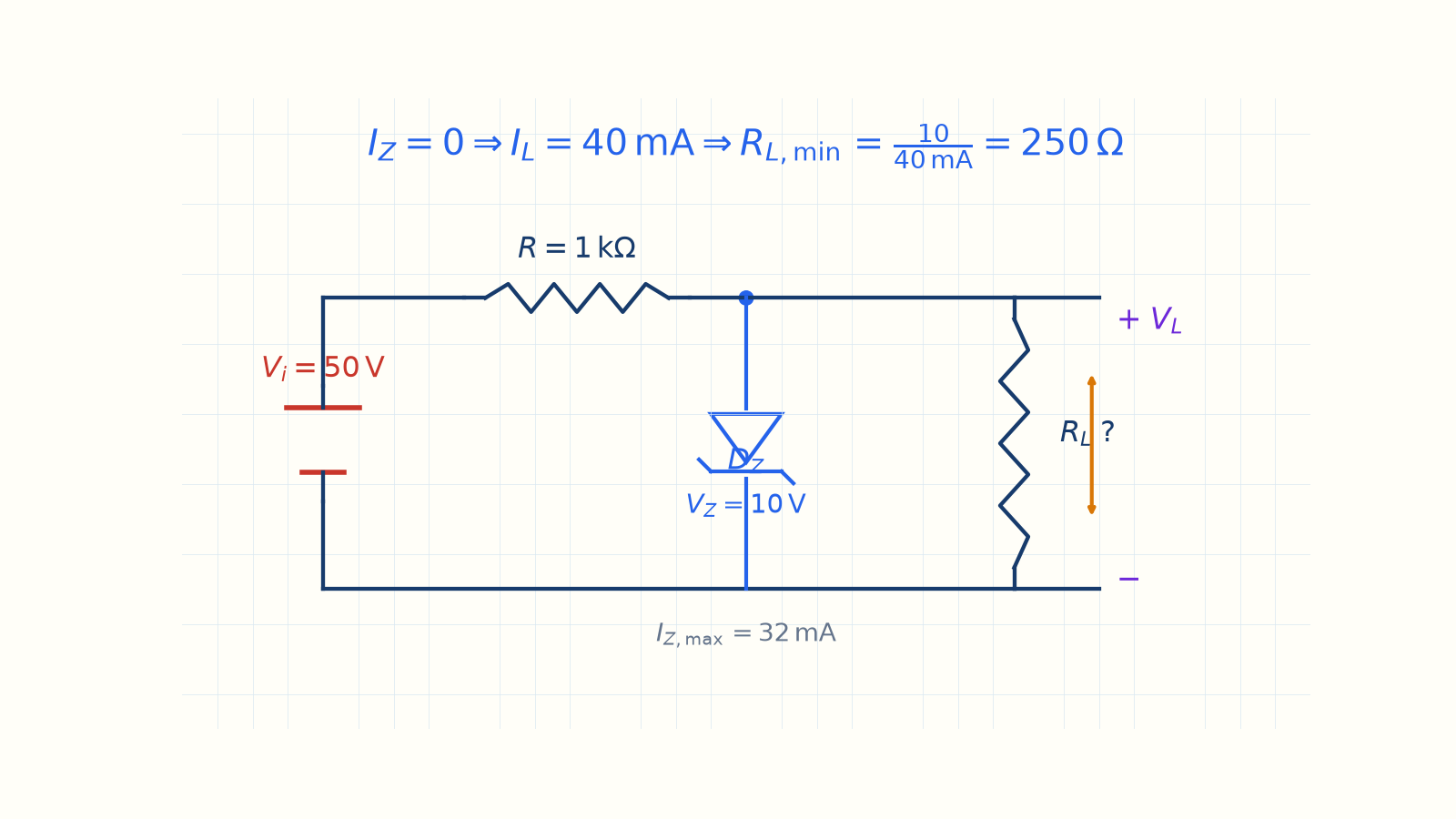
The result is R_L,min = 250 Ω. Heaviest load → RL,minAt the edge, IZ = 0IL = IR = 40 mARL,min = 10/40 mA = 250 ΩSmaller RL → regulation lostNarration transcript
Now think about the heaviest load, the smallest R sub L. A heavy load wants a lot of current. The most the load can ever take is when the Zener gives up its entire share, when the Zener current drops to zero. At that edge, all forty milliamps flow into the load: I sub L equals I sub R equals forty milliamps. So the smallest load resistance is the output over that current: ten volts over forty milliamps. Ten divided by forty thousandths is two hundred fifty ohms. So R sub L min is two hundred fifty ohms. Any smaller, and the load demands more than forty milliamps, but the resistor cannot supply more, so the node drops below ten volts and the Zener switches off. That is the lower edge.
5. A — lightest load
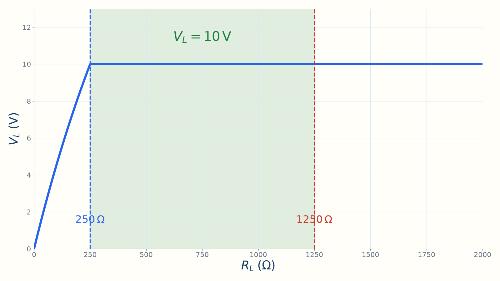
The output is fixed at 10 V inside the window. Lightest load → RL,maxAt the edge, IZ = 32 mAIL = 40 − 32 = 8 mARL,max = 10/8 mA = 1250 ΩInside the window, VL = 10 VNarration transcript
Now the opposite: the lightest load, the largest R sub L. A light load takes very little current, so the Zener has to swallow the rest. But the Zener can only take up to thirty-two milliamps. At that limit, the load gets whatever is left: forty minus thirty-two, which is eight milliamps. So the largest load resistance is ten volts over eight milliamps. Ten divided by eight thousandths is one thousand two hundred fifty ohms. So R sub L max is twelve hundred fifty ohms. Any larger, and the load takes less than eight milliamps, so the Zener current climbs past thirty-two and it burns. So the window is: R sub L between two hundred fifty ohms and twelve hundred fifty ohms. Inside it, the output holds at a clean ten volts.
6. B — fixed load
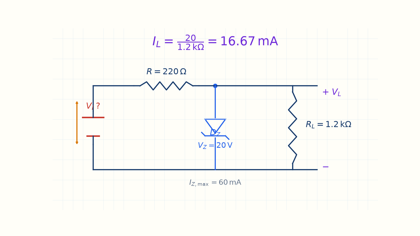
Load current remains fixed at 16.67 mA while the Zener regulates. IZ,max = 60 mARL = 1.2 kΩ; Vi is variableIL = 20/1.2 kΩ = 16.67 mAIL is fixed; input changes IRNarration transcript
Second case, the mirror image. Now the load is fixed at one point two kilo-ohms, and the input voltage is what changes. The resistor is two hundred twenty ohms, the Zener is twenty volts, and its maximum current is sixty milliamps. Here the easy insight flips. While the Zener is on, the output is pinned at twenty volts across a fixed load, so the load current is fixed. Twenty volts over one point two kilo-ohms is 16.67 milliamps. That I sub L never changes; what changes is how much the input pushes through the resistor.
7. B — lowest input
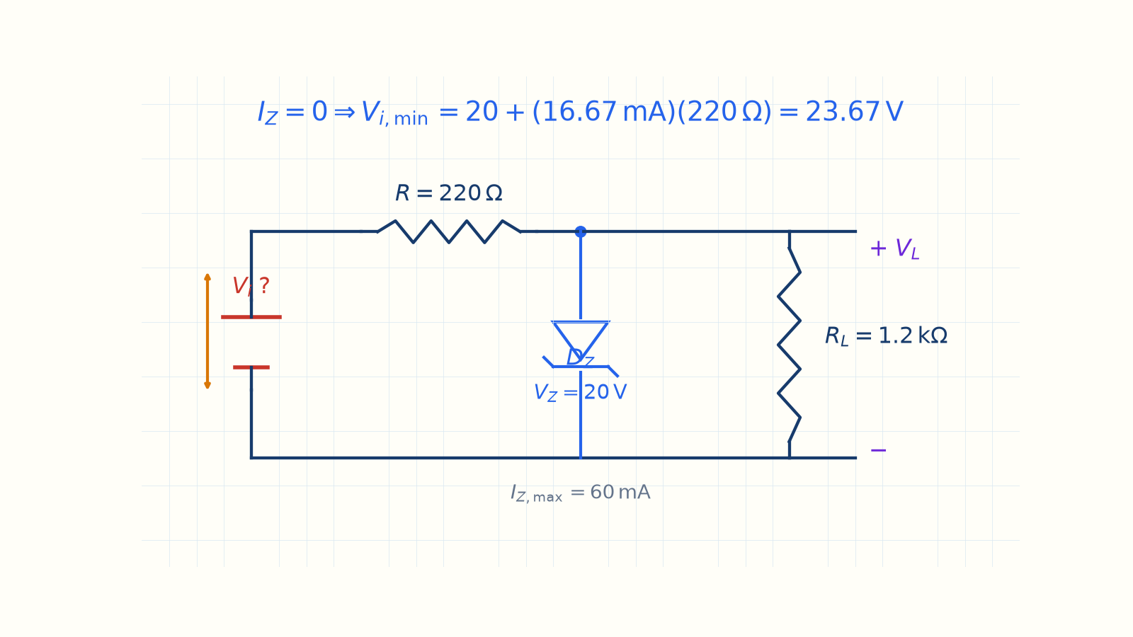
The result is V_i,min = 23.67 V. Lowest input → Vi,minAt the edge, IZ ≈ 0IR = IL = 16.67 mAVi,min = 20 + 16.67 mA·220 ΩNarration transcript
What is the lowest input that still regulates? That is when the Zener is just barely on, its current almost zero. With no Zener current, the whole series current equals the load current: I sub R equals 16.67 milliamps. Now walk the loop: the input must supply the twenty volts across the Zener plus the drop across the resistor. That drop is I sub R times R: 16.67 milliamps times two hundred twenty ohms, about 3.67 volts. So V in min is twenty plus 3.67, which is 23.67 volts. Below that, the input cannot even reach twenty volts at the node, and regulation is lost.
8. B — highest input
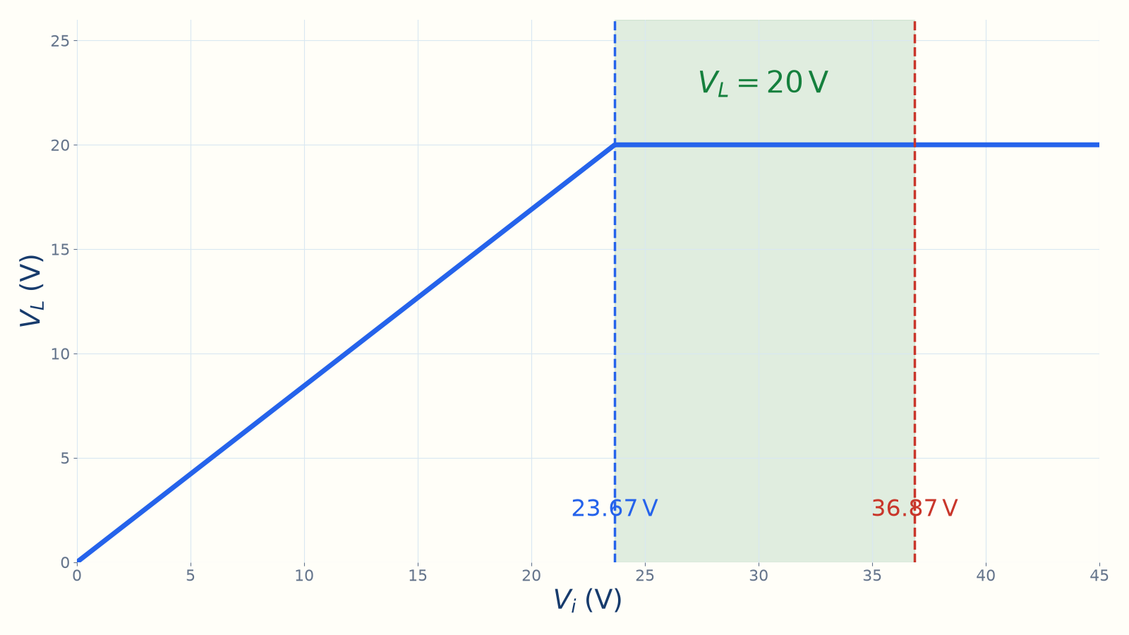
The output is fixed at 20 V inside the window. Highest input → Vi,maxAt the edge, IZ = 60 mAIR = 16.67 + 60 = 76.67 mAVi,max = 20 + 76.67 mA·220 ΩNarration transcript
And the highest input? That is when the Zener hits its limit, sixty milliamps. Now the resistor carries both the load and the full Zener current: I sub R equals 16.67 plus sixty, which is 76.67 milliamps. The resistor drop is 76.67 milliamps times two hundred twenty ohms, about 16.87 volts. So V in max is twenty plus 16.87, which is 36.87 volts. Above that, the Zener current passes sixty milliamps and it burns. So the window is: input between 23.67 and 36.87 volts, and across that whole range the output stays flat at twenty volts.
9. Method summary
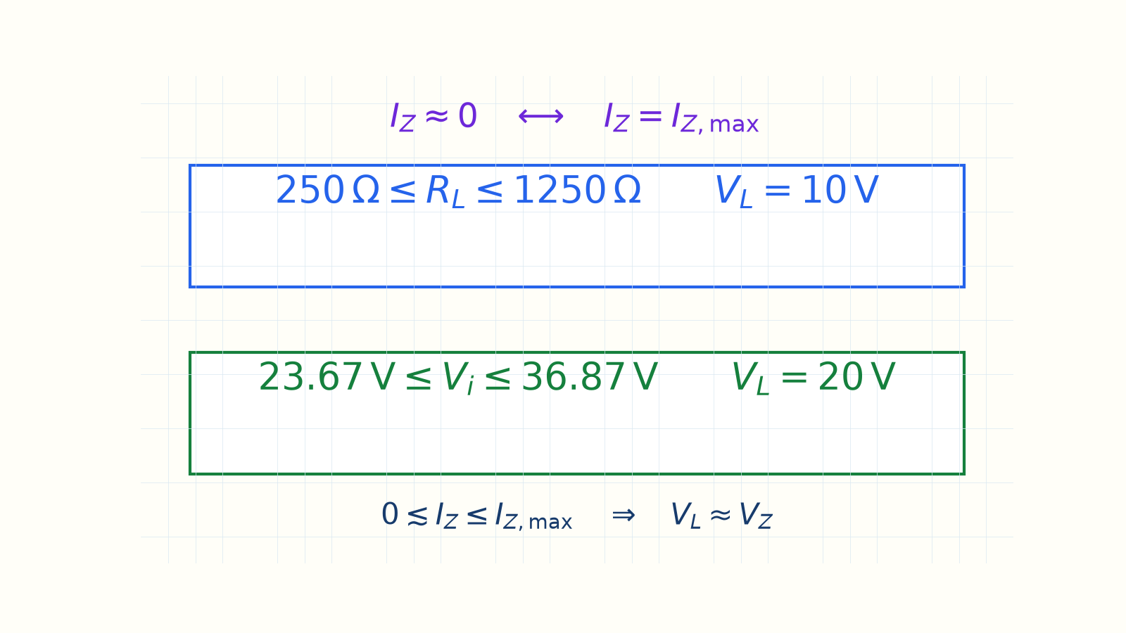
Load range: 250–1250 Ω; input range: 23.67–36.87 V. 1) Set VL = VZ while regulating2) Find the branch current that stays fixed3) Use IZ ≈ 0 at the lower edge4) Use IZ = IZ,max at the upper edge5) Join both limits into the safe windowTwo edges → the regulator operating rangeNarration transcript
Let us bring it together. A Zener regulator only works inside a window, set by two limits, and they are always the same two. The lower edge is the Zener barely on, its current near zero. The upper edge is the Zener at its maximum current, its power limit. We found the window twice. With a fixed fifty-volt supply, the load may range from two hundred fifty ohms to twelve hundred fifty ohms. With a fixed load, the input may range from about twenty-four to thirty-seven volts. Inside each window, the output is a flat plateau at V sub z. The rule: find the two edges, Zener just on, and Zener at I sub z max, and you have defined the regulator. Next, we leave diodes behind and meet the device that powers almost all of modern electronics: the transistor.
Source video: Electronics Basics #13 | Zener Regulator: The Safe Window (R_L & V_in Ranges) (7:19)