Electronics 1 · Electronics Basics
#11 Clamper variations — five worked examples
Solve five examples showing how diode and DC-source orientation set the clamp level, and verify Vpp preservation in every result.
Question
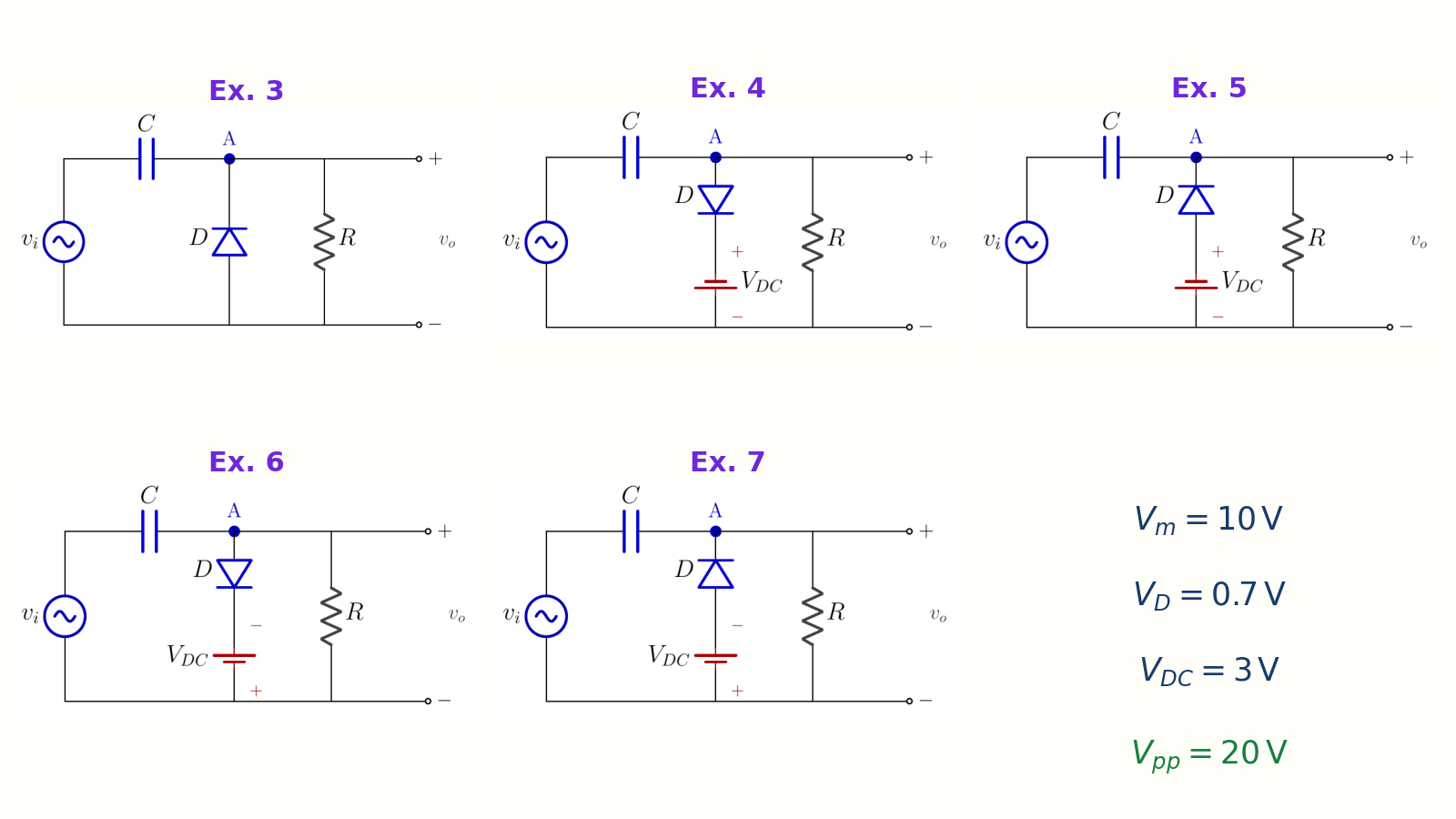
For a square wave with 10 V peak and a silicon diode with V_D = 0.7 V, determine the output limits of the five clamper circuits. Use V_DC = 3 V in the biased examples. For each circuit, identify the conducting half-cycle, clamp level, and capacitor voltage, then verify that the output retains a 20 V peak-to-peak span.
Written solution and narration transcript(shows the full solution)
Below are all the lines written in the notebook together with the full narration transcript.
1. Common solution method
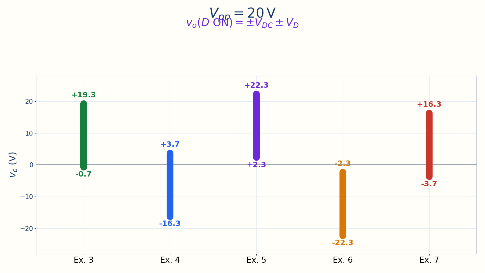
Every interval preserves 20 V peak to peak while its DC position changes. Common skeleton: series C, shunt D, load RD ON → output clamps and C chargesD OFF → VC shifts the waveformClamp level = diode direction, VD, and VDCFor these examples Vpp,out = 20 VNarration transcript
Welcome back. In the previous lesson we built one clamper, and added one bias source. But there are many more configurations. Today we will work through five worked examples that cover every bias combination you will encounter. Here is the key insight. Every clamper has the same skeleton: a series capacitor, a diode, and a load resistor. When the diode turns on, the output is clamped to a fixed level we will call the clamp level. When the diode turns off, the output equals the input plus or minus the capacitor voltage. The clamp level is determined by two things: the diode forward drop V sub d, and the DC bias voltage V sub DC. Together they form four sign combinations: plus or minus V sub DC, plus or minus V sub d. That gives us four biased examples. Plus one baseline example with no bias at all. Five examples. Five different clamp levels. Five different output positions on the y-axis. Same rule, every time: peak-to-peak is preserved at two V sub m.
2. Example 3
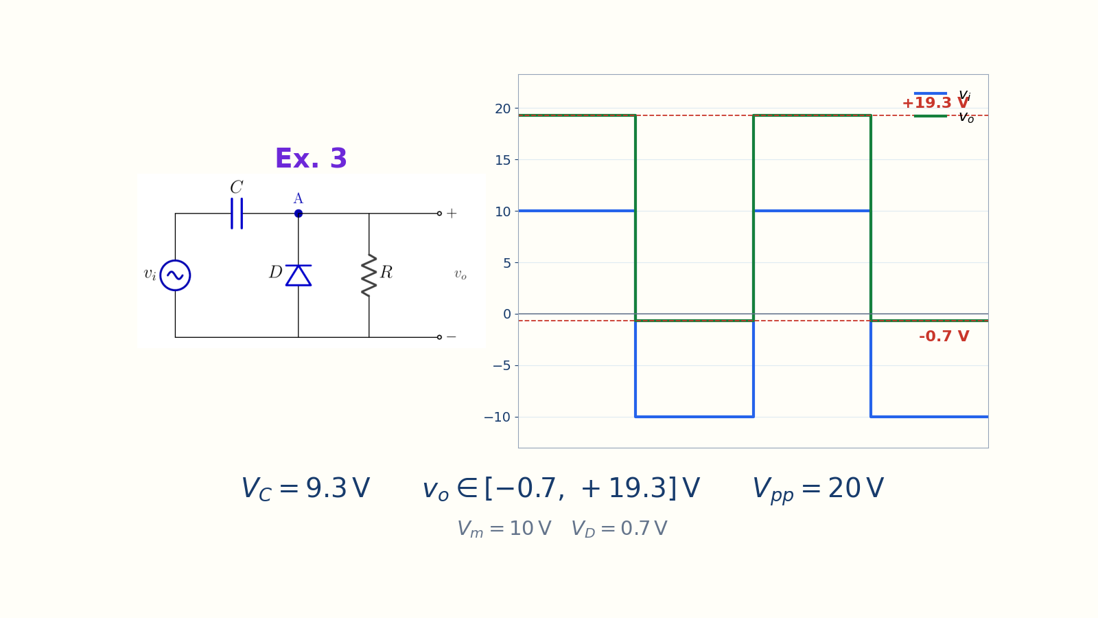
The output ranges from minus 0.7 V to plus 19.3 V. No bias; diode points upwardvo ∈ [−0.7, +19.3] VNarration transcript
Example three. The baseline case: a silicon diode pointing up, no bias source. Input is a ten volt peak square wave, swinging from plus ten to minus ten volts. When the input is negative, the diode is forward biased. The output is clamped to negative V sub d, that is minus 0.7 volts. While the diode is on, the capacitor charges. V sub C equals V sub m minus V sub d, which is ten minus 0.7, equals 9.3 volts. When the input swings to plus ten, the diode turns off. The output equals input plus capacitor voltage, ten plus 9.3, equals plus 19.3 volts. So the output range is from minus 0.7 to plus 19.3 volts. Peak-to-peak is twenty volts, exactly matching the input.
3. Example 4
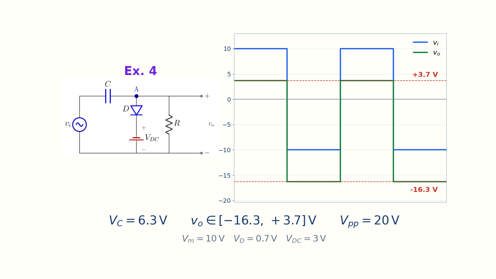
The output ranges from minus 16.3 V to plus 3.7 V. Downward diode; upper clampvo ∈ [−16.3, +3.7] VNarration transcript
Example four. Same circuit but the diode is flipped, pointing down. And we add a three volt DC bias in series with the diode, with the positive terminal on the cathode side. Now the diode conducts during the positive half-cycle, when the input is plus ten. The clamp level becomes plus V sub DC plus V sub d, which is three plus 0.7, equals plus 3.7 volts. The capacitor charges to V sub m minus V sub DC minus V sub d, which is ten minus three minus 0.7, equals 6.3 volts. When the input swings to minus ten, the diode turns off. The output drops to input minus capacitor voltage, minus ten minus 6.3, equals minus 16.3 volts. Output range: from minus 16.3 to plus 3.7 volts. Peak-to-peak twenty, preserved.
4. Example 5
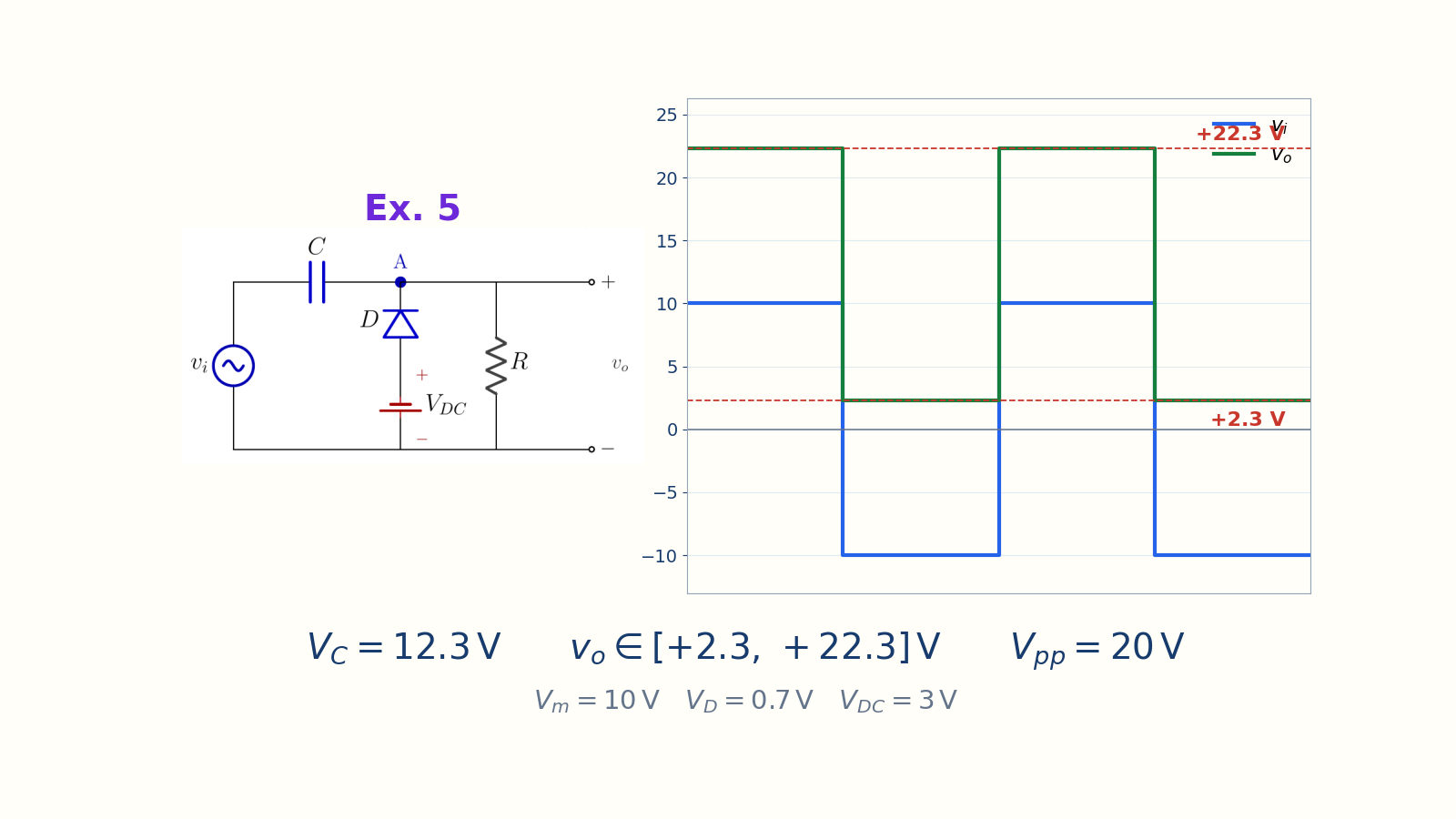
The output is entirely positive, from plus 2.3 V to plus 22.3 V. Upward diode; positive lower limitvo ∈ [+2.3, +22.3] VNarration transcript
Example five. The diode points up, like example three. But now we add a three volt DC bias with the positive terminal on the anode side, helping the diode turn on. The diode conducts during the negative half-cycle. The clamp level is plus V sub DC minus V sub d, which is three minus 0.7, equals plus 2.3 volts. The capacitor charges to V sub m plus V sub DC minus V sub d, ten plus three minus 0.7, equals 12.3 volts. During the positive half-cycle, the diode turns off. Output equals input plus capacitor voltage, ten plus 12.3, equals plus 22.3 volts. Look at the result: the output ranges from plus 2.3 to plus 22.3 volts. The entire waveform sits in positive territory. Peak-to-peak twenty, still preserved.
5. Example 6
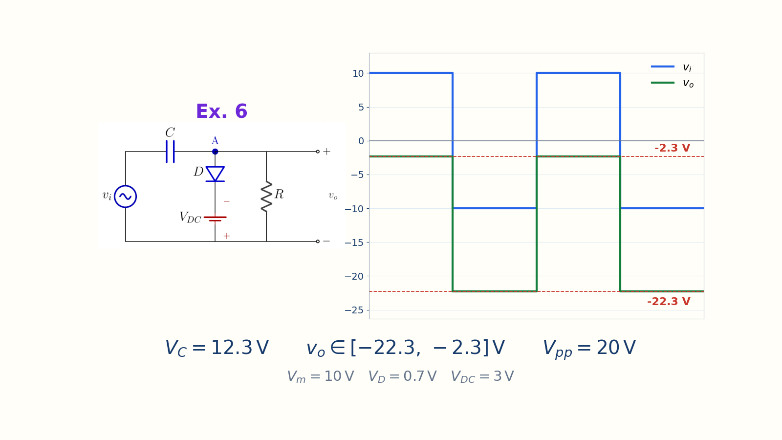
The output is entirely negative, from minus 22.3 V to minus 2.3 V. Downward diode; negative upper limitvo ∈ [−22.3, −2.3] VNarration transcript
Example six. Now flip the diode to point down again. Bias V sub DC is on the ground side, pulling the diode cathode into negative territory. The diode conducts during the positive half-cycle. But because of the bias, the clamp level is minus V sub DC plus V sub d, which is minus three plus 0.7, equals minus 2.3 volts. The capacitor charges to V sub m plus V sub DC minus V sub d, ten plus three minus 0.7, equals 12.3 volts. During the negative half-cycle, the diode turns off. Output equals minus ten minus 12.3, equals minus 22.3 volts. Output range: from minus 22.3 to minus 2.3 volts. The entire waveform sits in negative territory. Mirror image of example five. Peak-to-peak twenty.
6. Example 7
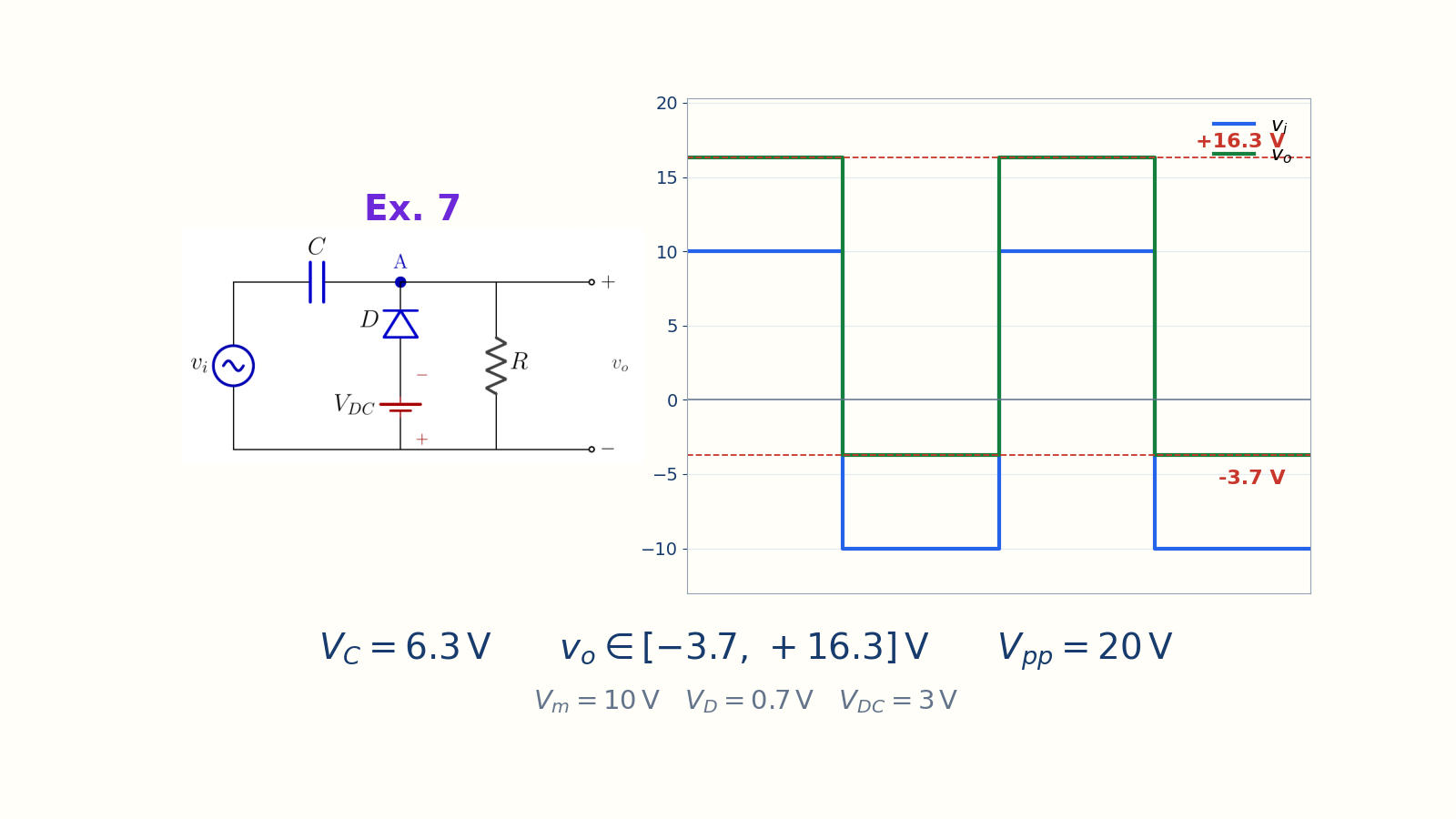
The output ranges from minus 3.7 V to plus 16.3 V. Upward diode; negative lower limitvo ∈ [−3.7, +16.3] VNarration transcript
Example seven. The last variation. The diode points up. Bias V sub DC is on the ground side, opposing the diode's natural conduction. The diode conducts during the negative half-cycle. The clamp level is minus the quantity V sub DC plus V sub d, which is minus three minus 0.7, equals minus 3.7 volts. The capacitor charges to V sub m minus V sub DC minus V sub d, ten minus three minus 0.7, equals 6.3 volts. During the positive half-cycle, the diode turns off. Output equals plus ten plus 6.3, equals plus 16.3 volts. Output range: from minus 3.7 to plus 16.3 volts. Peak-to-peak twenty volts. Five examples, five different positions on the y-axis.
7. Summary of five results
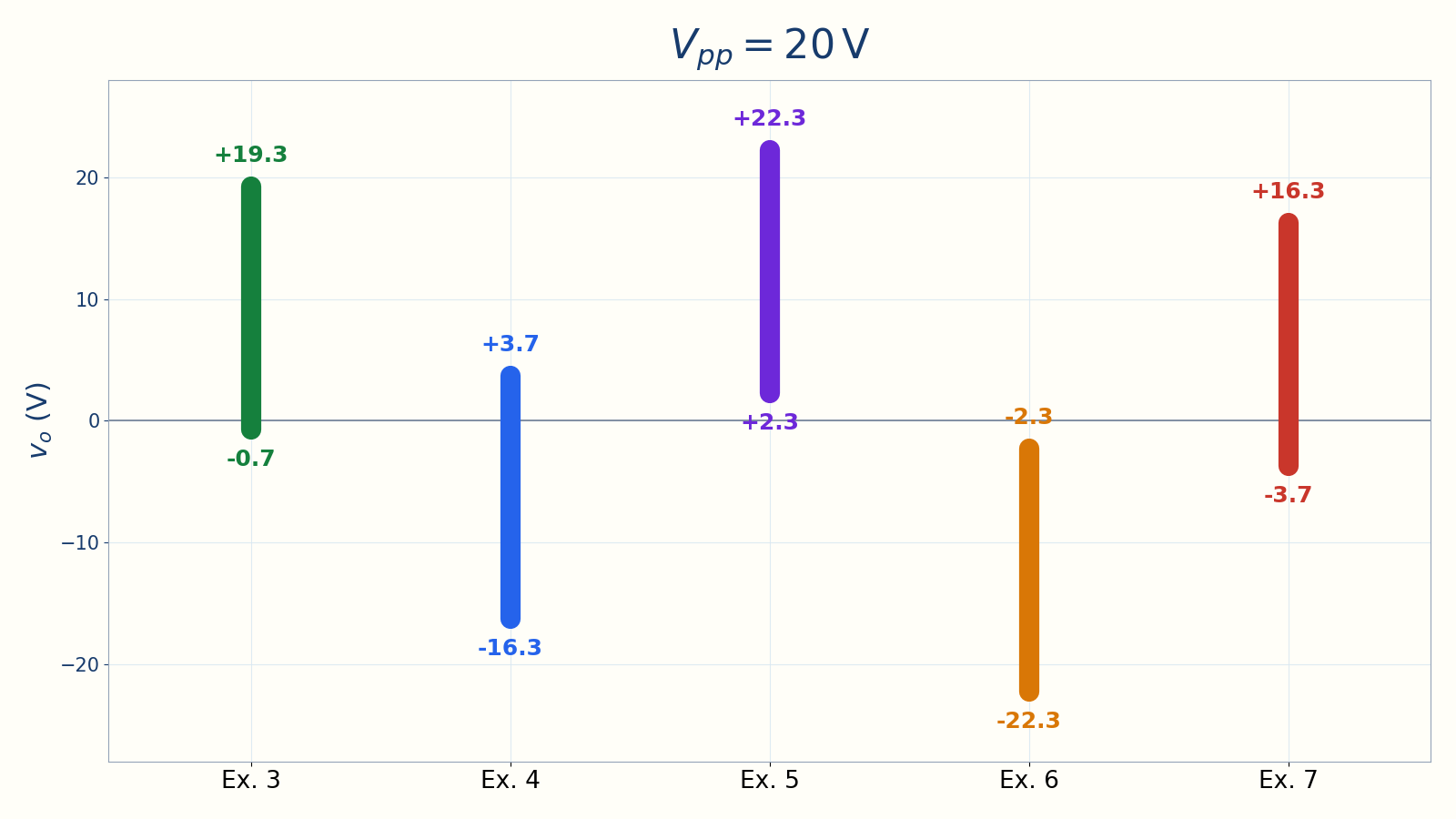
The difference between the upper and lower limits is 20 V in every example. Example 3 → [−0.7, +19.3] VExample 4 → [−16.3, +3.7] VExamples 5/6 → entirely positive/negativeExample 7 → [−3.7, +16.3] VMethod: D ON → clamp → |VC| → D OFFCheck:Narration transcript
Let us look at all five examples side by side. Example three sits from minus 0.7 to plus 19.3, the baseline with no bias. Example four sits from minus 16.3 to plus 3.7, bias pushes the clamp positive but most of the swing goes down. Example five sits from plus 2.3 to plus 22.3, entirely positive output. Example six sits from minus 22.3 to minus 2.3, entirely negative output. Example seven sits from minus 3.7 to plus 16.3, mostly positive with a small negative excursion. Five completely different output positions, all from the same basic clamper skeleton. The takeaway: by choosing the diode direction and the bias source polarity, you can place the output anywhere on the y-axis. And no matter where you place it, the peak-to-peak voltage is always preserved. In the next lesson, we introduce a different device with its own clamping behavior: the Zener diode.
Source video: Electronics Basics #11 | Clamper Circuit Variations: Five Worked Examples (7:54)