Electronics 1 · Electronics Basics
#22 JFET fixed bias — a candidate is not a verified operating point
Question
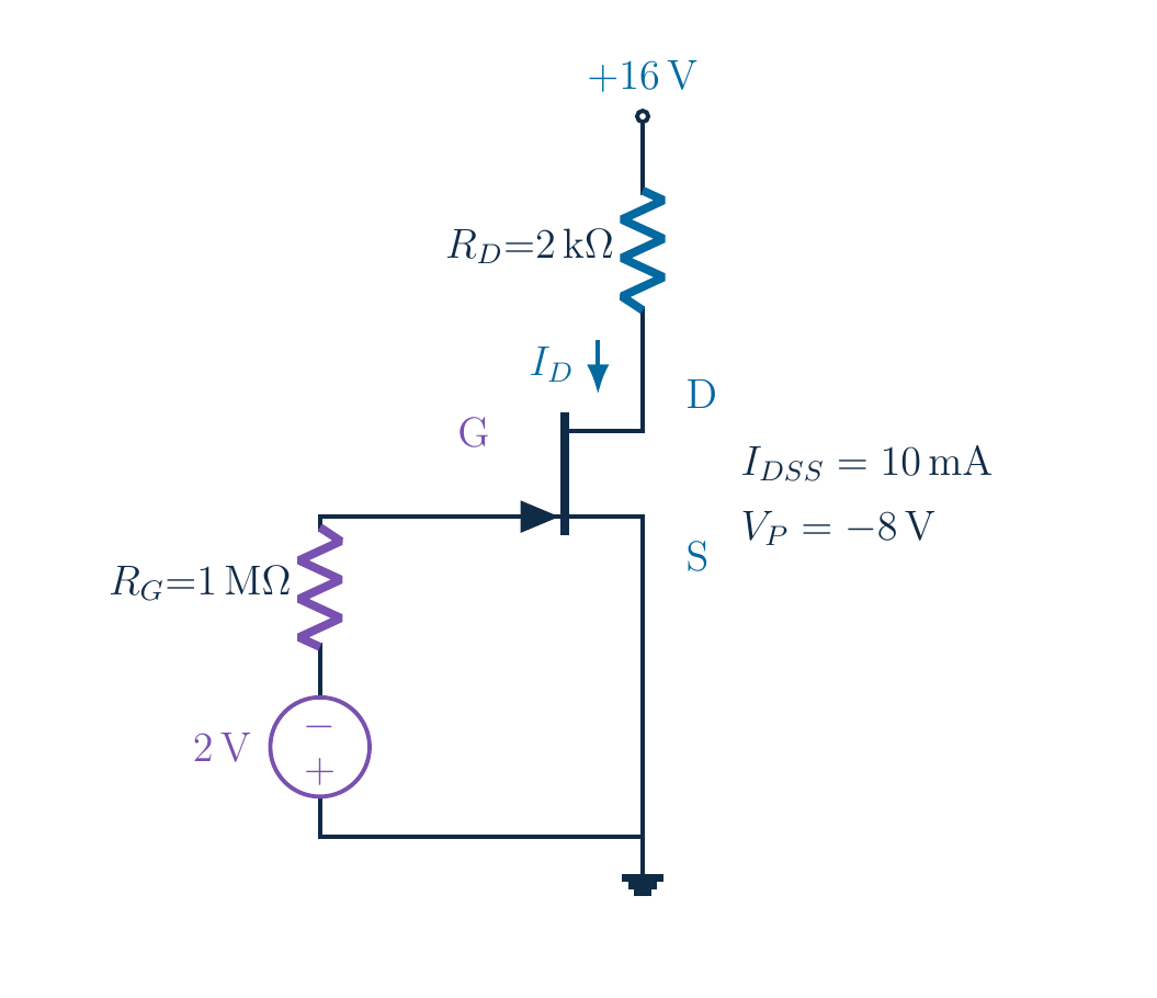
Find gate, source and drain voltages and drain current for the original 16 V fixed-bias circuit. R_D=2 kΩ, R_G=1 MΩ, gate supply −2 V, I_DSS=10 mA and V_P=−8 V. Check the saturation assumption. Keep the separate 20 V design comparison explicitly separate.
Written solution and narration transcript(shows the full solution)
Below are all the lines written in the notebook together with the full narration transcript.
1. The goal: find the DC operating point
DC bias sets the resting conditionFind VG, VS, VD and ID; verify the operating pointNarration transcript
Before a transistor can respond to a small signal, it needs a sensible resting condition. That is the purpose of DC bias. Today, find the gate, source and drain voltages, and the drain current, in this fixed-bias J FET circuit. Keep the whole circuit in view. Our goal is not just a number: it is an operating point that the circuit can actually support.
2. The goal: find the DC operating point
Original:Separate gate supply: −2 V relative to groundIDSS=10 [mA] · VP=−8 V · Source groundedNarration transcript
These are the original lesson's values. The drain supply is sixteen volts, the drain resistor is two kilohms, and the gate resistor is one megohm. A separate two-volt source holds the gate side negative relative to ground. The J FET parameters are ten milliamps for I D S S and negative eight volts for V P. The source terminal is connected directly to ground.
3. The goal: find the DC operating point
Wiring → VGS → candidate IDResistor drop → VDS → region checkThe original calculation needs a region-consistency checkNarration transcript
We will follow a simple order. First read the gate-source voltage from the wiring. Then calculate a candidate drain current with Shockley's equation. Next use the drain resistor to find the remaining drain voltage. Finally check whether the saturation assumption was valid. That last step matters here: the older worked calculation contains a region-consistency problem, and we are going to make it visible rather than hide it.
4. Start at ground; read the gate voltage
Ideal wire to ground → VS = 0 VGround is a reference, not a zero-current conditionNarration transcript
Always start with the reference node. The source is connected to ground by an ideal wire, with no source resistor in between. Therefore the source potential is zero volts. Ground does not mean that no current flows; it simply defines our zero-voltage reference. This makes the voltage bookkeeping especially clear in a fixed-bias circuit.
5. Start at ground; read the gate voltage
Reverse-biased gate:Large R alone creates no drop; leakage neglectedNarration transcript
The gate junction is reverse biased, so the steady gate current is approximately zero. Apply Ohm's law to the one-megohm resistor: voltage drop equals gate current times gate resistance. Approximately zero current gives approximately zero volts across that resistor. A large resistance does not create a voltage drop by itself. In real hardware leakage is not exactly zero, but we neglect it in this DC model.
6. Start at ground; read the gate voltage
Gate supply: positive at ground → negative node is −2 VNegligible RG drop → VG = −2 VNarration transcript
Now inspect the two-volt source polarity. Its positive terminal is at ground, and its negative terminal is on the gate-resistor side. That node is negative two volts, not positive two. With essentially no resistor drop, the gate is also at negative two volts. Gate-source voltage means gate potential minus source potential. Negative two minus zero gives negative two volts. The first terminal minus the second: keep that habit.
7. A saturation candidate, step by step
Assume saturation; label ID a candidateThe drain circuit must still support this assumptionNarration transcript
Assume saturation for the moment, and clearly label the result as a candidate. Shockley's equation is drain current equals I D S S times the square of one minus V G S divided by V P. Substitute ten milliamps, negative two volts and negative eight volts. We have not proved the operating region yet. This equation is a conditional model, not permission to ignore the drain circuit.
8. A saturation candidate, step by step
Subtract before squaring; retain both minus signsNarration transcript
Work inside the brackets first. Negative two divided by negative eight is positive one quarter. The two minus signs cancel, and the volts cancel as well. Next, one minus one quarter is three quarters. If you prefer decimals, one minus zero point two five is zero point seven five. Do not square too early, and do not lose either negative sign during substitution.
9. A saturation candidate, step by step
ID(candidate) = 5.625 [mA]Keep precision; saturation is not verified yetNarration transcript
Now square three quarters: three times three over four times four gives nine sixteenths. Multiply by ten milliamps. Ten times nine is ninety, so we get ninety divided by sixteen milliamps. That equals five point six two five milliamps. Keep the three decimal places for now; early rounding would change the later voltage drop. This is still the saturation candidate, not our final verified answer.
10. The supply voltage must be shared
Supply voltage = resistor drop + transistor voltageDo not insert a fixed diode-junction dropNarration transcript
Move to the drain loop. The sixteen-volt supply is shared between the drain resistor and the J FET. Starting from the supply and moving down the current direction, subtract the resistor drop, then subtract the drain-source voltage, and return to ground. Kirchhoff's voltage law gives sixteen minus drain current times two kilohms minus V D S equals zero. No extra diode-style fixed voltage belongs in this equation.
11. The supply voltage must be shared
Resistor drop is not the transistor voltageNarration transcript
Calculate the resistor drop with the candidate current. Five point six two five milliamps times two kilohms gives eleven point two five volts. Why volts directly? Milli means one thousandth, and kilo means one thousand. Their factors cancel. Numerically, five point six two five times two is eleven point two five. Keep this voltage drop separate from the voltage across the transistor.
12. The supply voltage must be shared
VDS(candidate) = 16 − 11.25 = 4.75 VVS = 0 → VD(candidate) = 4.75 VCorrect KVL arithmetic does not prove saturationNarration transcript
Subtract that drop from the supply. Sixteen minus eleven point two five leaves four point seven five volts from drain to source. Since the source is at zero volts, drain potential has the same numerical value. Check the voltage sum: eleven point two five plus four point seven five is sixteen. The arithmetic and Kirchhoff's law agree, but that alone does not establish saturation.
13. The missing check changes the conclusion
Required:Gate interval passes: −8 ≤ −2 ≤ 0; check VDS nextNarration transcript
Now apply the check from the previous lesson. With our signed n-channel convention, saturation requires drain-source voltage to be at least V G S minus V P. Here that is negative two minus negative eight. Subtracting a negative adds eight, so negative two plus eight gives six volts. The gate-voltage check passes because negative two lies between negative eight and zero. What about the drain voltage?
14. The missing check changes the conclusion
4.75 V < 6 V → saturation assumption FAILS5.625 [mA] and 4.75 V are not a verified operating pointNarration transcript
Our candidate gave only four point seven five volts. That is less than six volts. The saturation assumption fails. This is the missing qualification in the old worked result. Five point six two five milliamps and four point seven five volts are internally correct arithmetic under an assumption that this circuit does not satisfy. Do not report them as a verified physical operating point.
15. The missing check changes the conclusion
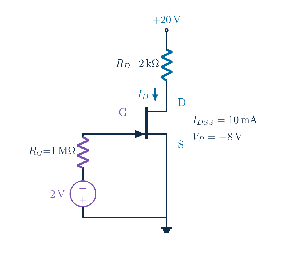
Next: a separate 20 V design, not the original 16 V circuit. An invalid saturation model does not mean zero currentNeed output characteristics or a fuller model; no invented currentRejecting an invalid assumption is a useful resultNarration transcript
Does that mean the real transistor stops conducting? No. It means this saturation-only formula is not sufficient for the original circuit. A more complete device model or the actual output characteristics are needed to locate the operating point in the low-voltage region. We will not invent a precise physical current from incomplete device information. Recognizing the invalid assumption is itself an essential circuit-analysis result.
16. A separate design comparison: 20 V
Separate design comparison — not the original circuitChange only VDD: 16 V → 20 VKeep RD, RG, gate supply and device parameters unchangedNarration transcript
To finish with a valid saturation example, make one clearly labeled design comparison. This is a new variant, not a silent change to the original question. Raise only the drain supply from sixteen to twenty volts. Keep both resistors, the negative-two-volt gate supply and the device parameters unchanged. Can this extra supply voltage leave enough voltage across the J FET?
17. A separate design comparison: 20 V
Same candidate ID = 5.625 [mA]Same VRD = 11.25 V; more voltage available at drainNarration transcript
The source is still grounded. Gate current is still negligible, so gate-source voltage stays at negative two volts. Shockley's saturation candidate therefore stays at five point six two five milliamps. The drain-resistor drop also stays at eleven point two five volts. Raising the supply did not change the control voltage in this fixed-bias model; it changed the voltage available to the drain circuit.
18. A separate design comparison: 20 V
20 V variant:8.75 V > 6 V → ideal saturation check passesAssume adequate breakdown and power ratingsNarration transcript
Repeat the drain calculation with twenty volts. Twenty minus eleven point two five equals eight point seven five volts. Now eight point seven five is greater than six, so the ideal saturation check passes. Also confirm the voltage sum: eleven point two five plus eight point seven five equals twenty. This comparison assumes a device whose breakdown and power ratings are adequate; the simplified model does not remove those hardware limits.
19. A valid answer includes its assumptions
20 V variant:Ideal saturation: ID=5.625 [mA], under stated assumptionsNarration transcript
State the answer with its case label. For the separate twenty-volt design variant, source potential is zero, gate potential is negative two volts, and drain potential is eight point seven five volts. Therefore V G S is negative two volts and V D S is eight point seven five volts. The ideal saturation drain current is five point six two five milliamps. These values form a consistent candidate operating point under our stated assumptions.
20. A valid answer includes its assumptions
Original 16 V case: saturation candidate rejectedModel-based calculation + assumption checks = engineering answerNarration transcript
Keep the original sixteen-volt case separate. Its gate and source voltages were determined correctly, but its saturation-current calculation failed the drain-voltage check. The larger lesson is useful far beyond J FETs: solve with a model, then test the assumptions that allowed you to use that model. A tidy calculator result is not the same thing as a verified engineering answer.
21. A valid answer includes its assumptions
Ground → IG ≈ 0 → VGS → candidate ID → drop → regionNext: source-resistor self-bias and feedbackNarration transcript
Your fixed-bias checklist is now complete: ground first, negligible gate current, gate-source voltage, candidate current, resistor drop, and operating-region verification. Next we remove the separate gate-bias supply and let a source resistor create the bias. That is self-bias, and it introduces feedback between drain current and gate-source voltage. The same careful signs and final checks will still be essential.
Source video: Electronics Basics #22 | JFET Fixed Bias: Calculate, Then Check (10:18)