Electronics 1 · Electronics Basics
#23 JFET self-bias — solve both roots, verify the physical one
Question
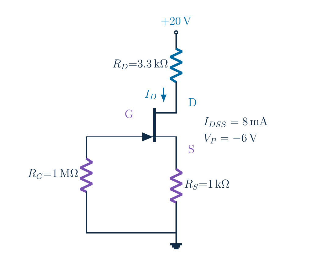
Find the resting operating point with one 20 V supply, R_D=3.3 kΩ, R_S=1 kΩ and R_G=1 MΩ to ground. I_DSS=8 mA and V_P=−6 V. Explain how a grounded gate can have negative V_GS. Solve both algebraic candidates and check the valid domain and saturation.
Written solution and narration transcript(shows the full solution)
Below are all the lines written in the notebook together with the full narration transcript.
1. The goal: bias without a second supply
Goal: ID and terminal voltages before adding a signalOne supply; source resistor creates the biasNarration transcript
Imagine preparing this transistor to amplify a small signal. Before adding that signal, we need to know where the device rests: its current, and the voltages at its three terminals. Today we will find that operating point using one supply. Keep the whole circuit in view. The important new element is the resistor underneath the source, which will create the negative gate-source bias for us.
2. The goal: bias without a second supply
No separate negative gate supplyNarration transcript
Read the original circuit values before calculating. The supply is twenty volts. The drain resistor is three point three kilohms, and the source resistor is one kilohm. A one-megohm resistor connects the gate to ground. The device parameters are eight milliamps for I D S S and negative six volts for V P. Notice that the separate negative gate supply from fixed bias has disappeared.
3. Grounded gate, positive source, negative bias
Gate resistor to ground → VG ≈ 0 VSource is not grounded: VGS need not be zeroNarration transcript
Start with the gate branch. We neglect the tiny reverse gate leakage in this ideal DC analysis. The gate current is approximately zero, so the voltage drop across the gate resistor is approximately zero as well. The bottom of that resistor is grounded. Therefore the gate potential is zero volts. This does not yet tell us the gate-source voltage, because the source is no longer connected directly to ground.
4. Grounded gate, positive source, negative bias
Grounded gate, raised source → negative VGSNarration transcript
With negligible gate current, essentially the same current flows through the drain and source resistors. Current through the source resistor creates a drop from the source down to ground, so the source becomes positive relative to ground. Now subtract source potential from gate potential. Zero minus I D times R S gives negative drain current times source resistance. A grounded gate can therefore have a negative gate-source voltage. The reference terminal matters.
5. Grounded gate, positive source, negative bias
ID ↑ → VS ↑ → VGS more negativeCurrent tends to fall: negative feedbackImproved stability ≠ perfect constant currentNarration transcript
This connection also explains the name self-bias. Suppose the current tries to increase. The source-resistor drop increases, the source rises, and the gate-source voltage becomes more negative. In the saturation model, that more-negative control voltage tends to reduce the current, opposing the original change. This is negative feedback. It improves stability, but it does not eliminate device variation or make a perfectly constant current source.
6. Turn the feedback into one equation
VGS = −ID RS; both relations must holdAssume saturation now; verify it after solvingNarration transcript
We now have two descriptions of the same operating point. Shockley's saturation equation links drain current to gate-source voltage. The source resistor links that same voltage back to drain current. We must satisfy both relations together. For now, assume saturation so that we can form a candidate solution. After finding the current and drain voltage, we will return to this assumption and check it explicitly.
7. Turn the feedback into one equation
x = ID/(1 [mA]): dimensionless; ID=x [mA]VGS=−x V; units remain explicitNarration transcript
Make the units explicit before expanding the equation. Define x equals drain current divided by one milliamp. The variable x is a dimensionless numerical value, so the current is x milliamps. Multiplying by the one-kilohm source resistor gives x volts at the source. Milli and kilo cancel. Therefore gate-source voltage is negative x volts. We are not dropping the units; we are choosing a clearly defined scaled variable.
8. Turn the feedback into one equation
The ratio is positive; the outer subtraction staysNarration transcript
Substitute the device parameters and the source-resistor relation into Shockley's equation. Divide the current equation by one milliamp. We obtain x equals eight times the square of one minus negative x divided by negative six. The two negative signs inside that ratio cancel. What remains is one minus x divided by six, all squared, and multiplied by eight. Keeping these signs visible prevents a common error in self-bias calculations.
9. Turn the feedback into one equation
Do not omit the cross termNarration transcript
Expand the square carefully. One minus x over six, squared, is one minus twice x over six plus x squared over thirty-six. Simplify the middle term to get one minus x over three plus x squared over thirty-six. Now multiply every term by eight. The right side becomes eight minus eight thirds times x, plus two ninths times x squared. The middle term is essential; squaring two terms separately would give the wrong equation.
10. Turn the feedback into one equation
Narration transcript
Clear the denominators by multiplying the entire equation by nine. The left side becomes nine x. On the right we have seventy-two minus twenty-four x plus two x squared. Subtract nine x from both sides. Negative twenty-four x minus nine x becomes negative thirty-three x. Rearrange into standard quadratic form: two x squared minus thirty-three x plus seventy-two equals zero. Each operation must affect both sides consistently.
11. Solve both roots; test their meaning
Narration transcript
Apply the quadratic formula with a equals two, b equals negative thirty-three, and c equals seventy-two. The discriminant is b squared minus four a c. Thirty-three squared is one thousand eighty-nine; four times two times seventy-two is five hundred seventy-six. Their difference is five hundred thirteen. Negative b is positive thirty-three, and two a is four. So x equals thirty-three plus or minus the square root of five hundred thirteen, divided by four.
12. Solve both roots; test their meaning
x₁ ≈ 2.588; x₂ ≈ 13.912 → currents in [mA]Keep both algebraic roots; use unrounded valuesPhysical domain decides, not “pick the smaller root”Narration transcript
Evaluate both signs. Using the minus sign gives approximately two point five eight eight, while using the plus sign gives approximately thirteen point nine one two. Since x was defined relative to one milliamp, these correspond to currents in milliamps. Both satisfy the expanded quadratic algebraically. We keep the unrounded values in the remaining calculations. Now the physical gate-voltage range, not a habit of choosing the smaller number, must decide which candidate is usable.
13. Solve both roots; test their meaning
Required:Large root → VGS ≈ −13.912 V: rejectSmall root → VGS ≈ −2.588 V: gate check passesNarration transcript
For this n-channel saturation transfer model, gate-source voltage must lie between negative six volts and zero. The larger root would make gate-source voltage about negative thirteen point nine one two volts, outside the allowed interval. Squaring the expression extended the algebra beyond the valid device domain. Reject that root. The smaller root gives approximately negative two point five eight eight volts, which passes the gate check. We still need to verify the drain voltage.
14. Recover every node voltage
Source rises; the gate does not fall below groundNarration transcript
Recover the source voltage first. Multiply the accepted candidate current by the one-kilohm source resistor. The source voltage is approximately two point five eight eight volts. The gate stays at zero volts, so zero minus that positive source voltage gives negative two point five eight eight volts from gate to source. This is the central picture of self-bias: the gate does not move below ground; the source rises above it.
15. Recover every node voltage
VD is relative to ground; it is not VDSNarration transcript
Next calculate the drain-resistor drop. Multiply the unrounded current in milliamps by three point three kilohms. The drop is approximately eight point five three nine volts. Starting at the twenty-volt supply, subtract that drop to reach the drain node. The drain potential is approximately eleven point four six one volts. This is a voltage relative to ground. It is not yet the drain-source voltage, because our source is above ground.
16. Recover every node voltage
8.872 V in the original: early-rounding differenceNarration transcript
Drain-source voltage means drain potential minus source potential. Subtract the source rise from the drain potential using the unrounded values. The result is approximately eight point eight seven three volts. Equivalently, subtract the current times the sum of both resistors from the supply. The original notes rounded the current early and obtained eight point eight seven two volts. That tiny difference is rounding, not a different circuit or a different operating principle.
17. Verify the region and the voltage sum
Saturation requires VDS ≥ VGS − VP8.873 V > 3.412 V → saturation check passesNarration transcript
Now check the assumption that allowed us to use Shockley's equation. Saturation requires drain-source voltage to be at least gate-source voltage minus V P. Here the threshold is negative two point five eight eight minus negative six, or approximately three point four one two volts. Our drain-source voltage, eight point eight seven three volts, is greater than the required threshold. Unlike the previous lesson's original fixed-bias circuit, this candidate passes the saturation check.
18. Verify the region and the voltage sum
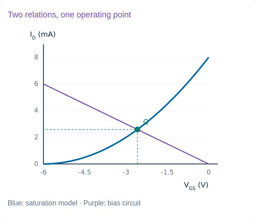
Original lesson graph; ideal DC model. Shockley substitution returns the same IDIdeal model: adequate ratings assumed; real parameters varyNarration transcript
Perform two final consistency checks. Along the drain-source loop, the drain-resistor drop, transistor voltage and source-resistor drop add back to twenty volts. Then substitute the unrounded current-derived gate voltage into Shockley's equation; it returns the same current. These checks support the ideal operating point. They do not certify an arbitrary physical part: we still assume adequate breakdown and power ratings, and real J FET parameters can vary significantly between devices.
19. A self-consistent operating point
Blue: Shockley curve · Purple: source-resistor relationIntersection satisfies both; drain-region check is separateNarration transcript
The graph gives a useful final view of the same calculation. The blue curve is the saturation transfer relation. The purple line comes from the grounded gate and source resistor. Their intersection selects the current and gate-source voltage that satisfy both equations. The drain circuit then passes the separate saturation test. Our operating point is about two point five eight eight milliamps and eight point eight seven three volts from drain to source.
20. A self-consistent operating point
Reference → bias relation → device equationAll roots → physical domain → voltages → region checkNext: common gate, with a smaller saturation marginNarration transcript
Remember the method, not just the final numbers. Establish the gate reference, express source voltage in terms of current, and combine the circuit relation with the device equation. Solve all mathematical candidates, then reject those outside the physical domain. Recover the remaining voltages and verify the operating region. In the next lesson, a common-gate DC circuit will use the same reasoning, but its available saturation margin will be much smaller.
Source video: Electronics Basics #23 | JFET Self-Bias — Step-by-Step DC Analysis (11:18)