Electronics 1 · Electronics Basics
#25 JFET divider bias — positive gate, negative gate-source voltage
Question
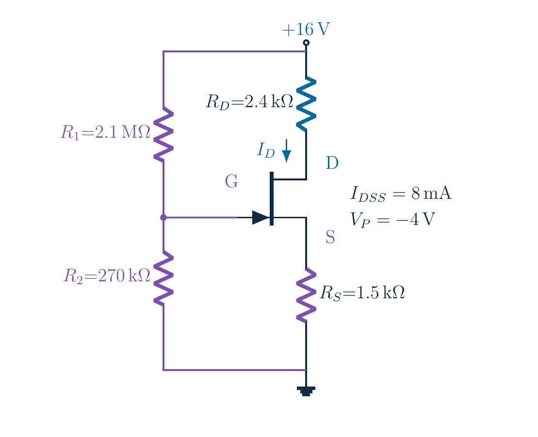
How can both gate and source be positive while V_GS is negative? Find the operating point for V_DD=16 V, R_D=2.4 kΩ, R_S=1.5 kΩ, upper divider resistor 2.1 MΩ, lower resistor 270 kΩ, I_DSS=8 mA and V_P=−4 V. Retain the divider precision and check both roots and saturation.
Written solution and narration transcript(shows the full solution)
Below are all the lines written in the notebook together with the full narration transcript.
1. The goal: a positive gate can still give negative bias
Question: positive gate, but nonpositive VGS?Source can be higher; every voltage needs a referenceNarration transcript
Look at this circuit before doing any algebra. A voltage divider will put the gate above ground, yet normal n-channel J FET bias still requires a nonpositive gate-source voltage in our model. How can both be true? The source can sit even higher than the gate. Our task is to find that self-consistent current and all the terminal voltages, keeping the reference for every voltage explicit.
2. The goal: a positive gate can still give negative bias
Divider: upper 2.1 MΩ; lower 270 kΩ; gate at junctionIDSS=8 [mA] · VP=−4 V; do not swap divider resistorsNarration transcript
Read the original values and positions. The supply is sixteen volts. The drain resistor is two point four kilohms and the source resistor one point five kilohms. In the divider, the upper resistor is two point one megohms, and the lower resistor is two hundred seventy kilohms. The gate connects to their junction. I D S S is eight milliamps and V P is negative four volts. Do not interchange the upper and lower divider resistors.
3. Use the unloaded divider to find the gate voltage
IG≈0: divider approximately unloadedNarration transcript
Why may we use the simple voltage-divider formula? We neglect gate leakage, so the gate draws essentially no current from the divider junction. The two resistors then carry the same divider current. Gate potential relative to ground is the voltage across the lower resistor. Therefore use the lower resistance in the numerator and the sum in the denominator. Convert two point one megohms to two thousand one hundred kilohms before combining the values.
4. Use the unloaded divider to find the gate voltage
Keep VG = 144/79 V internallyNarration transcript
Add the resistances: two thousand one hundred plus two hundred seventy is two thousand three hundred seventy kilohms. Multiply sixteen by two hundred seventy to get four thousand three hundred twenty. Divide by two thousand three hundred seventy. The gate voltage is approximately one point eight two three volts. Keep the full value, one point eight two two seven eight four eight one, internally. Rounding it now would slightly change the later current and voltage results.
5. Use the unloaded divider to find the gate voltage
Divider current ≠ gate current ≠ drain currentSmall divider current makes real leakage worth checkingNarration transcript
A useful check is the divider current. Sixteen volts divided by two point three seven megohms gives approximately six point seven five one microamps. This current travels through the two divider resistors even though the ideal gate current is zero. It is not the drain current we are about to solve for. In real hardware, a very small divider current can make leakage effects more important, so the unloaded-divider approximation must be assessed for the chosen device.
6. Combine the divider, source resistor and device
Do not drop the positive gate-voltage termNarration transcript
Now turn to the source resistor. Define x as drain current divided by one milliamp. Neglecting gate current, source current equals drain current, so the one point five kilohm resistor gives a source voltage of one point five x volts. Subtract that from the divider-established gate voltage. Gate-source voltage is one point eight two two seven eight four eight one minus one point five x, in volts. Do not reuse the grounded-gate formula without its new positive gate term.
7. Combine the divider, source resistor and device
Saturation still needs checkingNarration transcript
Assume saturation temporarily and substitute into Shockley's equation. V P is negative four volts, so subtracting V G S divided by negative four becomes adding V G S divided by four. Insert the gate-source expression. One plus the gate voltage divided by four is approximately one point four five five six nine six two zero two. The source term divided by four is zero point three seven five x. We have one current equation to solve, with the saturation assumption still waiting to be checked.
8. Combine the divider, source resistor and device
x = 8A2 − 6Ax + 1.125x2Narration transcript
Use a short dimensionless abbreviation, A, for one plus gate voltage divided by four volts. Expand the square of A minus zero point three seven five x. Multiplying by eight gives eight A squared, minus six A x, plus one point one two five x squared. Bring the left-hand x to the right. Its subtraction adds another negative x, so the linear coefficient is negative six A minus one. This step is easy to miss if you jump straight to calculator coefficients.
9. Combine the divider, source resistor and device
Use unrounded coefficients; displayed digits are not new measurementsNarration transcript
Substitute the divider-derived value of A. The quadratic coefficient is one point one two five. The linear coefficient is minus nine point seven three four one seven seven, continuing, and the constant is sixteen point nine five two four one one, continuing. These long decimals come from the divider ratio, not from new measurements. Use the unrounded values in the quadratic formula. A shortened display should never silently become a lower-precision calculation.
10. Solve both roots and select the physical candidate
Candidates:Each root must pass the gate-voltage checkNarration transcript
Calculate b squared minus four a c. The discriminant is approximately eighteen point four six eight three five four, and its square root is about four point two nine seven four eight two. The denominator, two a, is two point two five. Evaluating both signs gives candidate currents of about two point four one six milliamps and six point two three six milliamps. As before, solving the quadratic is not the end: each candidate implies a gate-source voltage that must be checked.
11. Solve both roots and select the physical candidate
Large root: VGS≈−7.532 V, outside [−4 V, 0]Small root: VGS≈−1.802 V, within the domainGate potential alone cannot determine VGSNarration transcript
For the larger root, subtract one point five times the candidate current value from the positive gate voltage. The implied gate-source voltage is about negative seven point five three two volts, outside negative four to zero, so reject it. The smaller root gives about negative one point eight zero two volts, which lies inside the interval. This is why a positive gate potential is not enough to decide the operating condition: source potential changes the terminal-pair voltage.
12. Keep each voltage reference explicit
Both nodes positive; source higher → negative VGSNarration transcript
Compute source potential with the accepted current. One point five kilohms times the unrounded current gives approximately three point six two four volts. The gate is only about one point eight two three volts above ground. Subtract source potential from gate potential, using unrounded numbers, to get negative one point eight zero two volts. We have answered the opening question: both nodes are positive, but the source is higher, so gate-source voltage is negative.
13. Keep each voltage reference explicit
Different references require different subtractionsNarration transcript
For the drain branch, multiply the accepted current by two point four kilohms. The resistor drop is approximately five point seven nine nine volts. Subtract this drop from the sixteen-volt supply, leaving a drain potential of about ten point two zero one volts. Again, this is measured relative to ground. The source and gate have different nonzero potentials, so we must perform two different subtractions to obtain drain-source and drain-gate voltages.
14. Keep each voltage reference explicit
Narration transcript
Subtract source potential from drain potential to obtain approximately six point five seven six volts from drain to source. Now subtract gate potential from drain potential to obtain approximately eight point three seven eight volts from drain to gate. These are not interchangeable. As a cross-check, drain-gate voltage plus gate-source voltage equals drain-source voltage. The gate terms cancel algebraically. Always read the subscripts as the first terminal's potential minus the second terminal's potential.
15. Verify the operating region and the circuit
Threshold:6.576 V > 2.198 V: domain and saturation checks passAssume suitable breakdown and power ratingsNarration transcript
Verify the saturation assumption explicitly. Gate-source voltage minus V P is approximately negative one point eight zero two minus negative four, giving about two point one nine eight volts. The available drain-source voltage is about six point five seven six volts and exceeds this threshold. The candidate therefore passes both the gate-domain and saturation checks. As in the earlier examples, we assume a device with suitable breakdown and power ratings; those real limits are not supplied by the square-law equation.
16. Verify the operating region and the circuit
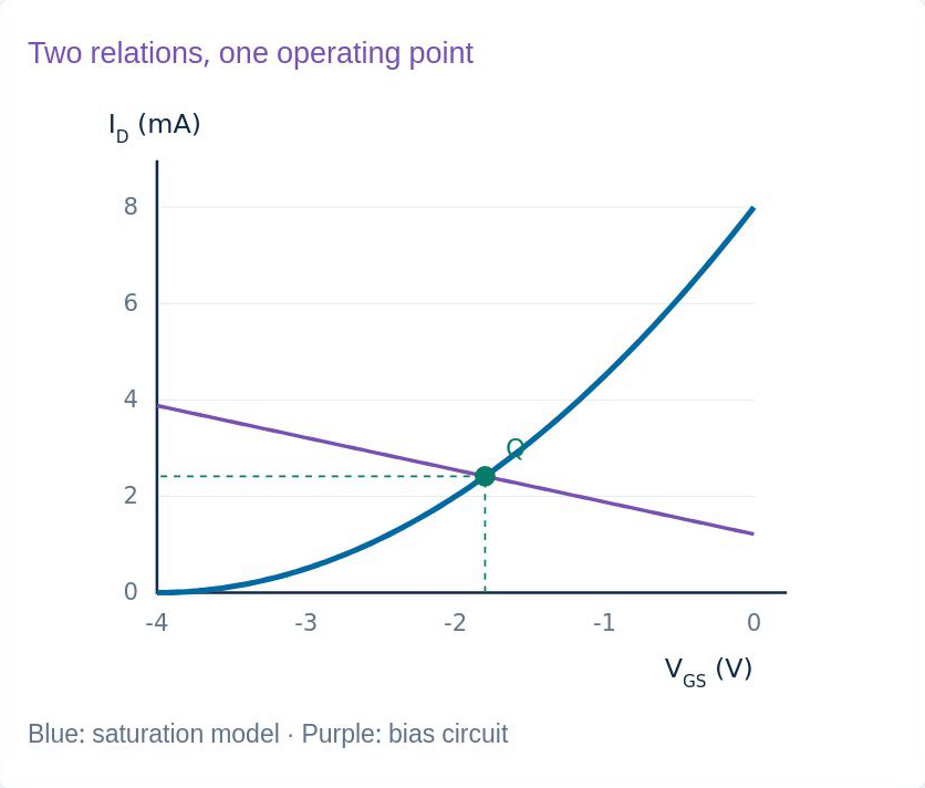
Original lesson graph; ideal DC model. Unrounded drops sum to 16 V5.799 + 6.576 + 3.624 = 15.999 V: display roundingShockley substitution returns the same currentNarration transcript
Add the three drops in the drain-source loop. Using unrounded numbers gives exactly the sixteen-volt supply within numerical precision. The displayed three-decimal values may add to fifteen point nine nine nine, which is a harmless rounding effect. Substitute the unrounded gate-source voltage into Shockley's equation and check that it returns the same current. These independent checks are more informative than trusting a single rounded final number on a calculator screen.
17. The complete, checked operating point
Circuit line:Accepted ideal current:Source above gate; negative VGS; drain check passesNarration transcript
The graph shows how divider bias differs from a grounded gate. The circuit line is now current equals gate voltage minus gate-source voltage, divided by source resistance. Its intersection with the transfer curve gives the accepted current and control voltage. The final ideal current is approximately two point four one six milliamps. Gate and source are both above ground, the source is higher, and the separately calculated drain voltage confirms a consistent saturation operating point.
18. The complete, checked operating point
Divider → bias relation → equation → roots → voltage checksSmall differences reflect retained precision, not changed componentsAlways ask: voltage relative to which terminal?Narration transcript
Keep the analysis in this order: find the unloaded divider voltage, express source voltage through current, combine the circuit with the device equation, and test every mathematical root. Then calculate the node and terminal-pair voltages and verify the operating region. Small differences from the original handwritten answers come from retaining more digits, not changing the component values. Most importantly, a positive gate voltage does not imply positive gate-source voltage: always ask, relative to which terminal?
Source video: Electronics Basics #25 | JFET Divider Bias — Positive Gate, Negative VGS (10:46)