Electronics 1 · Electronics Basics
#30 Enhancement MOSFET divider bias: gate voltage is not control voltage
Question
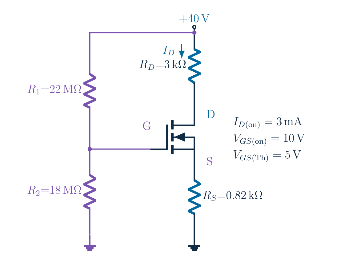
Find the DC operating point for V_DD=40 V, R_D=3 kΩ, R_S=0.82 kΩ and upper/lower divider 22 MΩ/18 MΩ. The device carries 3 mA at V_GS=10 V with V_T=5 V. Include the source rise and test both roots.
Written solution and narration transcript(shows the full solution)
Below are all the lines written in the notebook together with the full narration transcript.
1. The goal: find the operating point
40 V feeds divider and transistor branches separatelyFind ID, VGS and VDS; source rises with currentNarration transcript
Look at the whole circuit before doing any algebra. A forty volt supply feeds two separate paths. The resistors on the left set the gate voltage. The drain and source resistors on the right carry the transistor current. Our goal is to find that current and the two voltages that locate the operating point. The gate voltage alone is not the answer, because the source will rise above ground as current flows.
2. The goal: find the operating point
Enhancement n-channel MOSFET needs sufficient positive VGSRD=3 kΩ; RS=0.82 kΩ; divider 22 MΩ/18 MΩ; IG≈0Narration transcript
This is an enhancement mode, n channel MOSFET. Its broken channel symbol reminds us that positive gate to source voltage is needed to form a conducting channel. Keep the original values: three kilohms in the drain, zero point eight two kilohms in the source, and twenty two and eighteen megohms in the divider. We use an ideal insulated gate with negligible direct current, and later check whether our assumed transistor region is consistent.
3. Calibrate the enhancement device law
3 [mA] at VGS=10 V; VT=5 V; use overdrivek is full coefficient; no extra factor 1/2Narration transcript
The device data give three milliamps at a gate to source voltage of ten volts, with a threshold of five volts. The square law uses the voltage above threshold, not the entire gate to source voltage. In our notation, k is the full coefficient multiplying that squared excess. If another book puts one half in front of its coefficient, that coefficient has a different definition. We must not add an extra half here.
4. Calibrate the enhancement device law
k=1.2×10(−4) A/V2; keep [mA] and kΩ consistentNarration transcript
Calculate the coefficient from the specified on point. Three milliamps divided by the square of ten minus five volts gives zero point one two milliamps per volt squared. In amperes, the same value is one point two times ten to the minus four. We will keep currents in milliamps and resistances in kilohms, so their product is directly in volts. This consistent unit choice makes the next equations much easier to audit.
5. The divider sets the gate, not the source
Unloaded divider:VG=40×18/40=18 V; reference is groundNarration transcript
Because the gate takes negligible current, the left divider is unloaded in this model. The gate voltage is the supply multiplied by the lower resistance over the sum of the two resistances. Forty times eighteen divided by forty gives eighteen volts. Notice that the lower resistor belongs in the numerator. Also notice that this is a voltage measured from the gate to ground, not from the gate to the source.
6. The divider sets the gate, not the source
Narration transcript
The source current is approximately the drain current, because the gate current is negligible. Therefore the source resistor raises the source voltage by the drain current times zero point eight two kilohms. Subtract that rise from the fixed eighteen volt gate potential. The circuit relation is gate to source voltage equals eighteen minus zero point eight two times the drain current in milliamps. This is the connection between the divider and the nonlinear device.
7. Solve the current and reject the false root
Overdrive becomes (13−0.82x) Vx=0.12(13−0.82x)2; candidate saturation modelNarration transcript
Now combine the two relations instead of guessing a current. Replace gate to source voltage in the square law by the circuit expression. Subtracting the five volt threshold leaves thirteen minus zero point eight two times current. Call the numerical current in milliamps x. We obtain x equals zero point one two times the square of thirteen minus zero point eight two x. The square law is still a candidate model, so a solution must later pass the region checks.
8. Solve the current and reject the false root
Linear term includes cross term and moved −xNarration transcript
Expand carefully and then move x to the right side with the other terms. The coefficient of x squared is zero point zero eight zero six eight eight. The linear coefficient is minus three point five five eight four, and the constant is twenty point two eight. All three belong to the same equation. In particular, the linear term contains both the cross term from the square and the extra minus x. Dropping either contribution changes the operating point.
9. Solve the current and reject the false root
Candidates: ID≈6.725 [mA] and 37.376 [mA]Two algebraic roots ≠ two valid operating points; test domain and supplyNarration transcript
The discriminant is positive, so the quadratic produces two real candidates. Solving gives about six point seven two five milliamps and thirty seven point three seven six milliamps. They are mathematical candidates, not two valid operating points. Squaring a voltage difference loses information about its sign. We must return to the physical enhancement condition and the supply circuit before accepting either root.
10. Solve the current and reject the false root
Large root → VGS≈−12.65 V < VT=5 VReject; resistor drops would also exceed 40 VNarration transcript
Test the larger current first. Its source voltage would exceed the gate voltage, giving a negative gate to source voltage of about minus twelve point six five volts. That is below the positive five volt threshold, so the assumed enhancement channel cannot conduct according to the model. Reject the larger root. It would also demand more voltage across the drain and source resistors than the forty volt supply can provide. Two independent checks expose the same nonphysical result.
11. Solve the current and reject the false root
Small root → VS≈5.514 VConducting; saturation still needs a VDS checkNarration transcript
For the smaller root, retain the unrounded current in the calculation. It gives a source rise of about five point five one four volts. Subtracting from eighteen leaves a gate to source voltage of about twelve point four eight six volts, safely above the five volt threshold. This root passes the conduction check. We still need the drain to source voltage, because being on does not automatically mean operating in saturation.
12. Check the supply loop and saturation
Full loop:Round at end; early current rounding can shift about 1 [mV]Narration transcript
Use the entire supply loop. The forty volts must cover the drain resistor drop, the transistor drain to source voltage, and the source resistor drop. The two resistors add to three point eight two kilohms. Subtracting their combined drop gives a drain to source voltage of about fourteen point three one two volts. If the handwritten solution rounds the current earlier, its final voltage can differ by about one millivolt. That is rounding, not a different circuit.
13. Check the supply loop and saturation
Overdrive:14.312 V > 7.486 V: saturation consistent; no breakdown guaranteeNarration transcript
For an ideal conducting enhancement MOSFET, saturation requires drain to source voltage to be at least the gate overdrive. The overdrive is gate to source voltage minus threshold, which is about seven point four eight six volts here. Our fourteen point three one two volts is greater, so the saturation check passes. This confirms that the square law we used is consistent with the resulting circuit voltages. It is a direct current model check, not a breakdown voltage guarantee.
14. Check the supply loop and saturation
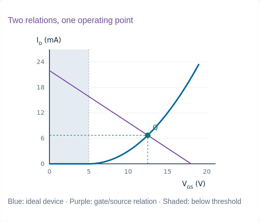
Original lesson graph; ideal model. KVL returns 40 V; device law returns same IDIdiv=40 V/(40 MΩ)=1 [μA]; real leakage/loading can matterNarration transcript
We can now verify the answer in two independent equations. In the supply loop, the resistor drop plus the transistor voltage adds back to forty volts. In the device law, the coefficient times the squared overdrive returns the same drain current. Remember also that the divider carries only one microamp in the ideal calculation. Real leakage and measurement loading can matter with megohm resistances, so the ideal unloaded divider assumption must be stated explicitly.
15. Connect the circuit, device and operating point
Device above 5 V threshold meets source-feedback linePhysical intersection only; graph does not replace saturation testNarration transcript
The graph connects the algebra back to the circuit. The blue device curve begins at the five volt threshold. The purple straight line comes from the fixed gate voltage and the source resistor: increasing current raises the source and reduces gate to source voltage. Their physical intersection is the operating point we accepted. The rejected algebraic branch is not an extension of the enhancement channel below threshold. The graph is a check on the equations, not a replacement for the saturation test.
16. Connect the circuit, device and operating point
Identify device → k → divider → source rise → nonlinear equationReject invalid roots; verify voltages and region; VG ≠ VGSNarration transcript
Keep this sequence for the next circuit. First identify the transistor type and the quantities you need. Then calculate the device coefficient and the unloaded gate voltage. Include the source resistor before solving the nonlinear equation. Reject roots outside the physical model, find the remaining voltages, and finally test the operating region. The essential distinction is simple: the divider sets gate voltage, but the transistor responds to gate to source voltage.
Source video: Electronics Basics #30 | Enhancement MOSFET: Voltage-Divider Bias (8:53)