Circuit Theory 1 · Operational Amplifiers
#33 Operational Amplifiers #33 — Non-inverting op-amp gain
Derives the non-inverting gain from a conditional virtual copy and the feedback divider, then solves a 6 V example with a rail check.
Question
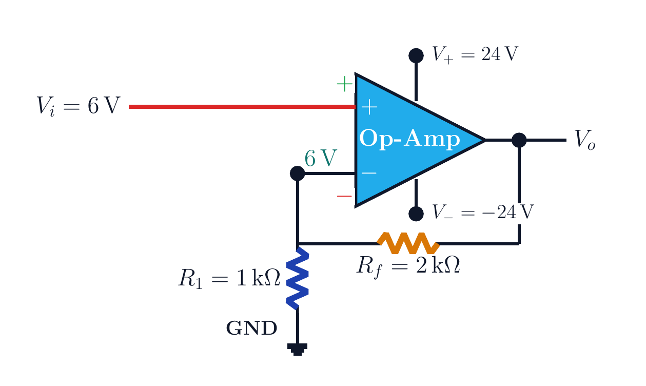
For an ideal non-inverting op amp with V_i at the plus input, R_f from output to the minus input, and R_1 from the minus input to ground, derive V_o/V_i. Find the output for V_i=6 V, R_1=1 kΩ, R_f=2 kΩ, and ±24 V supplies, then interpret the rail limit.
Written solution and narration transcript(shows the full solution)
Below are all the lines written in the notebook together with the full narration transcript.
1. Question and circuit
The circuit is used to calculate positive gain and check whether the ideal output fits within the rails. Non-inverting op-amp questionVi → plus inputRf: Vo to minus inputR1: minus input to groundFind Vo and AvNarration transcript
Here is the exact question for this lesson. We have a non-inverting op amp. The input signal V i goes directly into the plus input. The minus input is not grounded directly; instead, it sees a feedback divider made from R f and R one. First, we want the general relation between V output and V input. Then, in the example, V i is six volts, R one is one kilo ohm, R f is two kilo ohms, and the supply rails are plus and minus twenty four volts. We will find the output voltage and the voltage gain, step by step.
2. Conditional virtual copy
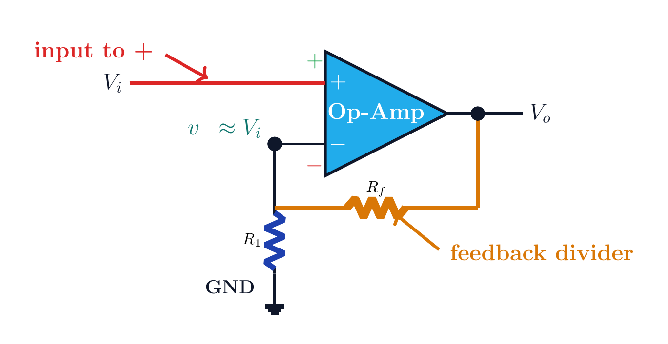
Under negative feedback, the minus node conditionally follows the input voltage. Conditional virtual copyNegative feedback is requiredOperation must be linear and unsaturatedIdeal model:This node is not virtual groundNarration transcript
The central idea is almost the same as before, but with one important change. In the inverting amplifier, the plus input was grounded, so the minus node became a virtual ground. Here the plus input is not ground. It is V i. With negative feedback and an ideal op amp in its linear region, the output moves until v minus becomes almost equal to v plus. Since v plus equals V i, the minus node becomes almost equal to V i. So this time it is not virtual ground. It is more like a virtual copy of the input voltage.
3. Feedback divider
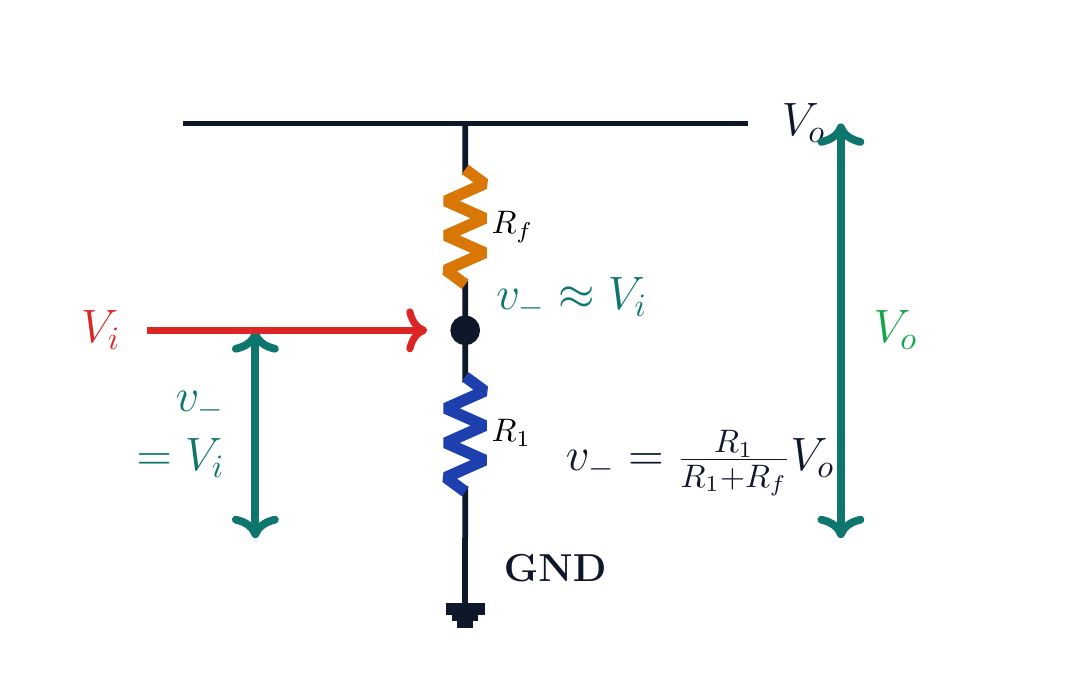
With zero ideal input current, the middle node samples the output by the ratio R_1/(R_1+R_f). Feedback dividerIdeal input current:Rf and R1 are in series from output to groundThe divider is unloadedNarration transcript
Now look at the two resistors. The op amp input current is zero, so the minus input does not steal current from the divider. That means R f and R one behave like an ordinary voltage divider between V output and ground. The voltage at the middle node is the fraction R one over R one plus R f, multiplied by V output. But that same middle node is v minus, and feedback makes it approximately equal to V i. This is the whole trick.
4. Gain derivation
Under negative feedback, the minus node conditionally follows the input voltage. Derive the non-inverting gainPositive sign: no phase reversalNarration transcript
Now solve the formula slowly. We just said that V i equals R one over R one plus R f, multiplied by V output. To isolate V output, divide by that fraction. Dividing by R one over R one plus R f is the same as multiplying by R one plus R f over R one. So V output equals R one plus R f, over R one, times V input. Then we split the fraction into one plus R f over R one. Therefore the voltage gain is A v equals one plus R f over R one. Notice the sign: it is positive. This circuit does not invert the signal.
5. Numerical example
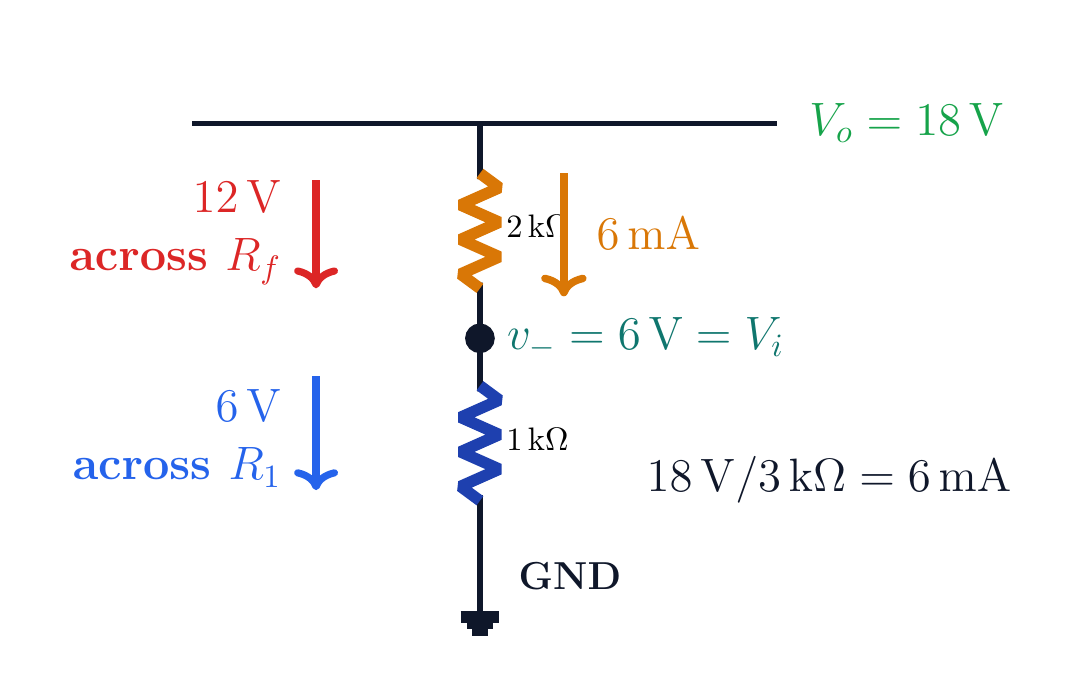
The 6 V across R_1 confirms that the minus node follows the input. Numerical examplei=18 V/(3 kΩ)=6 mA(6 mA)(1 kΩ)=6 VDivider and gain checks agreeNarration transcript
Now plug in the example numbers. R f over R one is two kilo ohms divided by one kilo ohm. The kilo ohm units cancel, so the ratio is two. The gain is one plus two, which is three. If V input is six volts, V output is three times six volts. Three times six is eighteen, so V output is eighteen volts. As a quick check, the total divider resistance is three kilo ohms. Eighteen volts over three kilo ohms gives six milliamps. That current through R one, one kilo ohm, gives six volts at the minus node, matching the input.
6. Supply check
The circuit is used to calculate positive gain and check whether the ideal output fits within the rails. Supply-rail checkIdeal demand:The ideal rail test passesWith ±12 V the output would clipCheck practical output swing in the data sheetNarration transcript
Before we accept the answer, check the supply rails. The example op amp is powered from plus twenty four volts and minus twenty four volts. Our calculated output is plus eighteen volts. Eighteen volts is inside the twenty four volt limit, so the ideal answer can fit. If the same circuit only had plus and minus twelve volt rails, eighteen volts would be too large and the output would clip. Here, with plus and minus twenty four volts, the answer is safe.
7. Waveform
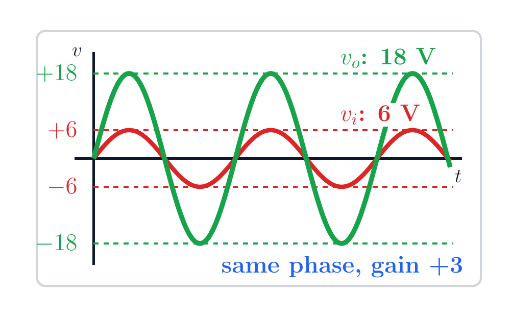
A gain of positive three preserves frequency and phase while tripling amplitude. Read the waveformAv>0 → same phaseZero crossings occur together6 V peak → ideal 18 V peakNarration transcript
What does that mean for a sine wave? The frequency does not change. The output has the same phase as the input, because the gain is positive. The amplitude becomes three times larger because the gain is three. So when the input is positive, the output is also positive. When the input crosses zero, the output crosses zero at the same time. This is why the circuit is called non-inverting.
8. Method summary
Under negative feedback, the minus node conditionally follows the input voltage. Method summary1. Identify the input at the plus terminal2. Verify the conditions for v−≈Vi3. Write the output dividerHere Av=3 and Vo=18 VFinal check: rails and practical output swingNarration transcript
The non-inverting op amp is read with three ideas. First, the input goes to the plus terminal. Second, feedback makes the minus terminal almost equal to that input, not necessarily zero. Third, the two feedback resistors form a voltage divider from output to ground. From those ideas, the formula follows naturally: V output equals one plus R f over R one, times V input. For this example, the gain is three and a six volt input gives an eighteen volt output.
Source video: Circuit Theory #33 | Non-Inverting Op-Amp: Positive Gain and 6 V Example (4:55)