Circuit Theory 1 · Source Transformation
#22 Source transformation #22 — find the voltage V
Transforms two Norton pairs into Thevenin equivalents, solves the resulting series loop, and recovers the marked voltage V.
Question
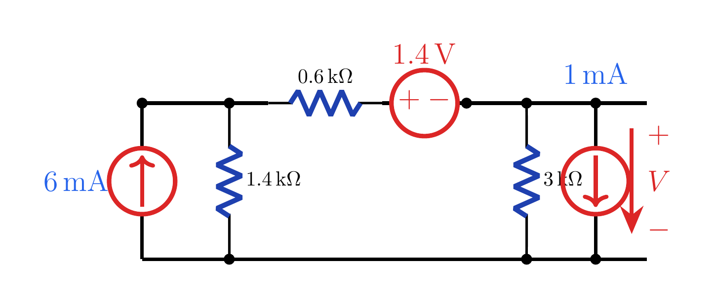
Use source transformation to find the voltage V with the polarity marked positive at the top.
Written solution and narration transcript(shows the full solution)
Below are all the lines written in the notebook together with the full narration transcript.
1. Transformation rule
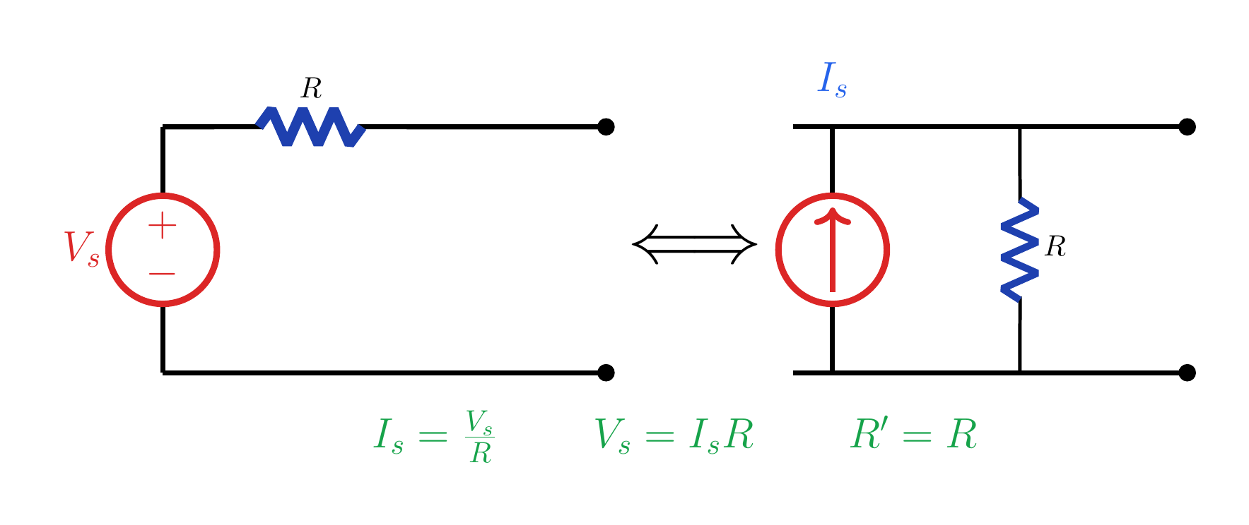
I_s=V_s/R and V_s=I_sR; the resistance is unchanged. Source transformationVs in series with R ⇔ Is in parallel with RThe resistor is unchanged:External terminal behavior is preservedNarration transcript
Source transformation is a way to replace one source model by another model that looks the same from the outside terminals. A voltage source V s in series with a resistor R can be replaced by a current source I s in parallel with the same resistor R. The value is I s equals V s divided by R. In the reverse direction, a current source I s in parallel with R becomes a voltage source V s equals I s times R in series with R. Only the external behavior is preserved, so the load connected to the terminals sees the same voltage and current.
2. Read the circuit
The red arrow marks voltage V with its top terminal positive. Read the circuit and targetTarget: V with + at the topLeft pair: 6 mA ∥ 1.4 kΩRight pair: 1 mA ↓ ∥ 3 kΩThe 0.6 kΩ resistor and 1.4 V source remainNarration transcript
Now use the method on a mixed source circuit. The target voltage V is measured at the right node, plus at the top and minus at the bottom. On the left, a 6 milliamp current source is in parallel with 1.4 kilo ohms. On the right, a 1 milliamp current source points downward and is in parallel with 3 kilo ohms. Those two source resistor pairs can be transformed, while the 0.6 kilo ohm resistor and the 1.4 volt source stay in the top branch.
3. Transform source pairs
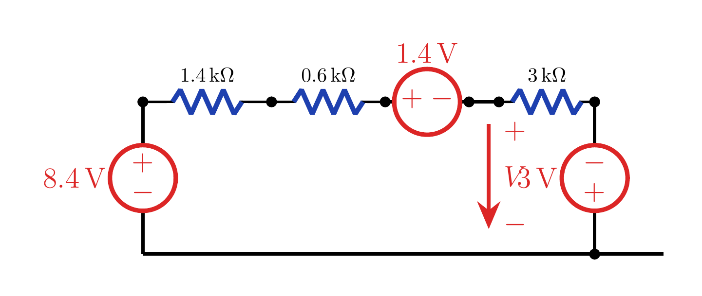
The left source is 8.4 V with top positive; the right source is 3 V with top negative. Transform both Norton pairsLeft: (6 mA)(1.4 kΩ)=8.4 VThe left source is + at the topRight: (1 mA)(3 kΩ)=3 VDownward arrow ⇒ − at the topNarration transcript
Transform the left Norton pair first. Six milliamp times 1.4 kilo ohms gives 8.4 volts, with the top terminal positive because the current source injects current upward into the top node. The parallel 1.4 kilo ohm resistor becomes a series 1.4 kilo ohm resistor. For the right pair, the 1 milliamp arrow points downward, so the top terminal is negative in the Thevenin form. One milliamp times 3 kilo ohms gives 3 volts, with minus at the top and plus at the bottom.
4. Loop current
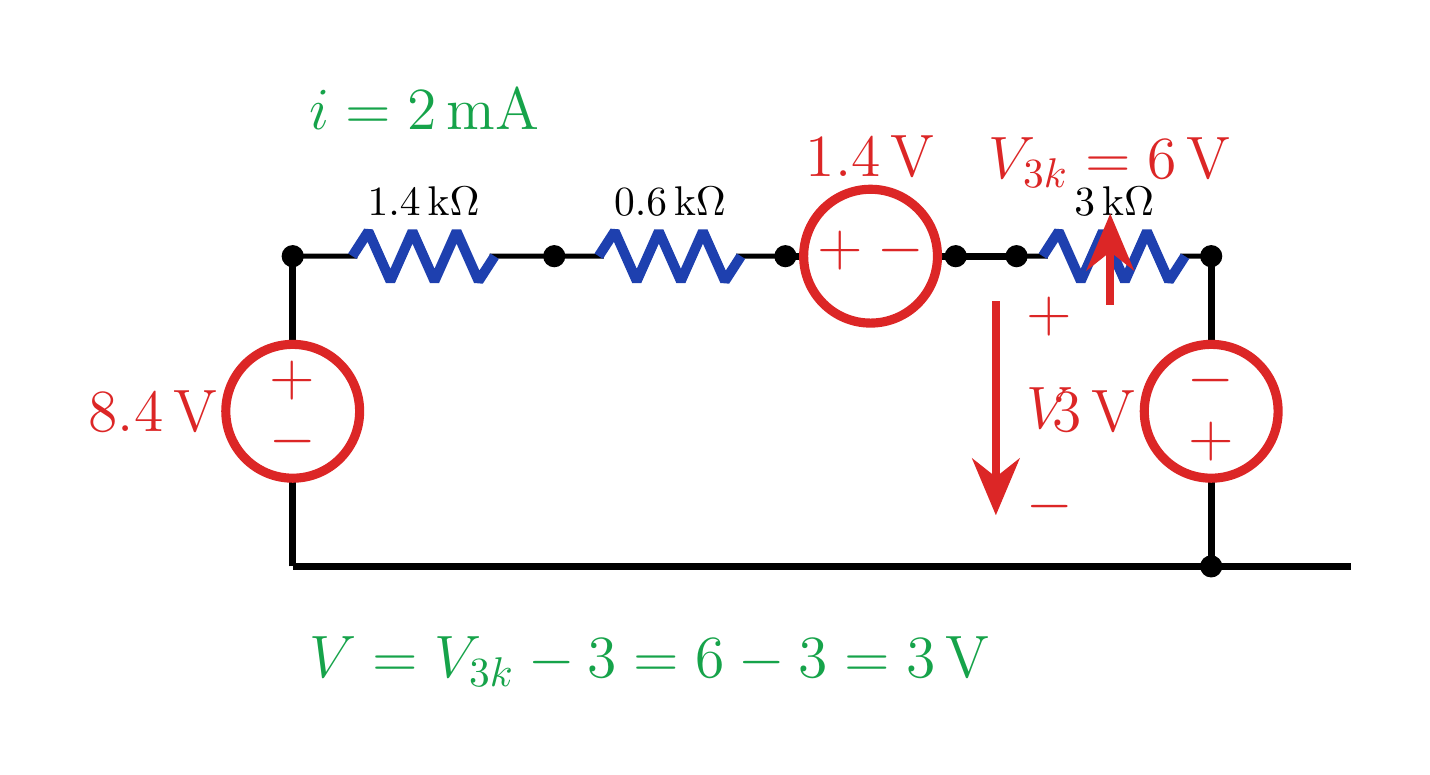
i=2 mA, V_{3k}=6 V, and V=6−3=3 V. Solve the single series loopVnet=8.4−1.4+3=10 Vi=Vnet/RTi=10 V/5 kΩ=2 mANarration transcript
After both transformations, the circuit becomes one series loop. The total resistance is 1.4 kilo ohms plus 0.6 kilo ohms plus 3 kilo ohms, which is 5 kilo ohms. Following the loop direction, the sources combine as 8.4 volts minus 1.4 volts plus 3 volts. That net source is 10 volts. Therefore the loop current i is 10 volts divided by 5 kilo ohms, or 2 milliamp.
5. Output voltage
i=2 mA, V_{3k}=6 V, and V=6−3=3 V. Recover the requested voltage VV3k=(3 kΩ)(2 mA)=6 VRight source: top −, bottom +Answer:Narration transcript
The current through the 3 kilo ohm resistor is 2 milliamp. So the voltage across that resistor is 3 kilo ohms times 2 milliamp, which is 6 volts. The output node is not directly across the whole 6 volts, because the 3 volt source on the right has minus at the top and plus at the bottom. With the marked polarity, V equals 6 volts minus 3 volts. The requested output voltage is therefore 3 volts.
6. Method summary
I_s=V_s/R and V_s=I_sR; the resistance is unchanged. Source-transformation checklistTransform only strict series or parallel pairsKeep the same resistanceUse I=V/R or V=IRMark polarity and arrow direction firstCheck:Narration transcript
The process is systematic. First identify a source and resistor that are strictly in series or strictly in parallel. Second, convert with I equals V divided by R or V equals I times R, keeping the same resistance. Third, track polarity and arrow direction carefully. In this example the downward 1 milliamp source is what makes the right Thevenin source have minus at the top. That sign is why the final output is 6 volts minus 3 volts, equal to 3 volts.
Source video: Circuit Theory #22 | Source Transformation Method - Find V (3:39)