Electronics 1 · Electronics Basics
#19 Two stacked BJTs — voltage-divider bias and DC analysis
Use one three-resistor divider to establish two base voltages, then solve the shared current and both V_CE values of two stacked BJTs.
Question
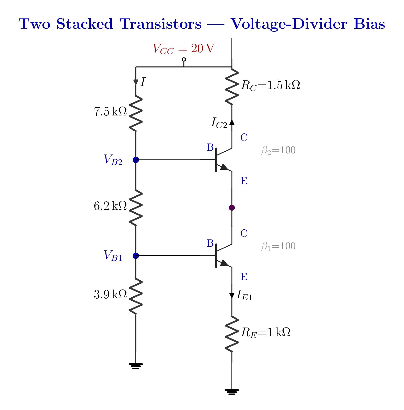
Two NPN BJTs are stacked in a circuit with V_CC = 20 V, divider resistors 7.5 kΩ, 6.2 kΩ, and 3.9 kΩ, R_C = 1.5 kΩ, and R_E = 1 kΩ. With a stiff divider and I_C ≈ I_E, find I_C1, I_C2, V_CE1, and V_CE2, then verify the results by KVL.
Written solution and narration transcript(shows the full solution)
Below are all the lines written in the notebook together with the full narration transcript.
1. Two transistors, one problem
One divider supplies two base voltages while the series transistor path carries one shared collector current. One three-resistor divider → two base tapsQ2 above Q1 in one stackFind IC1, IC2, VCE1, and VCE2One current path → IC2 ≈ IC1Two transistors are not two independent problemsNarration transcript
Welcome back. Over the last few lessons we tamed the voltage-divider bias: one divider sets the base, and the operating point barely cares about beta. Today we keep that idea and raise the stakes. Two transistors, stacked one on top of the other, sharing a single bias divider. And look at that divider on the left. Not two resistors now, but three. That longer ladder hands us two different base voltages at once, one for each transistor. Our job is to find four numbers: the collector current and the collector-emitter voltage of each transistor. Here is the picture to hold in your head. Imagine one pipe running top to bottom with two water turbines stacked inside it, one above the other. The same stream turns both. Whatever flows through the top turbine must flow through the bottom one too. That single shared flow is the key to the whole problem. It looks like twice the circuit, but it is not twice the work. Let us see why.
2. Read the topology
One divider supplies two base voltages while the series transistor path carries one shared collector current. Stiff divider:β1 and β2 drop outLower tap → VB1; upper tap → VB2VCC → RC → Q2 → Q1 → RE → groundSolve from the bottom upwardNarration transcript
Before any numbers, let us read the circuit and make three observations that turn it from scary into simple. First: one divider, two taps. The supply pushes a single current down through all three resistors in series, and we read off a voltage at each junction along the way. The lower junction feeds the base of the bottom transistor; the upper junction feeds the base of the top one. Second: one current path. Follow the heavy line. Out of the supply, through the collector resistor, down through the top transistor, straight into the bottom transistor, and out through the emitter resistor to ground. There is only one road, so the same current flows through both transistors. The top collector current equals the bottom collector current. We will lean on that hard. Third, the comfortable part: the divider is stiff, just like last time, so we ignore the tiny base currents, and beta never enters. Now the trap. It is tempting to think two transistors means two separate problems, each needing its own beta. It does not. They are chained together by that one shared current. So here is the plan: work from the bottom up. The bottom transistor's base and emitter resistor hand us the current directly, and once we have the current, everything else falls out.
3. Two base voltages
One divider supplies two base voltages while the series transistor path carries one shared collector current. I ≈ 1.136 mANarration transcript
Step one: the two base voltages, straight from the divider. Because we are treating the base currents as zero, nothing branches off into the transistors, so the divider is unloaded: one clean current down the ladder. That current is the supply over the total resistance. Add the three resistors: 7.5 k plus 6.2 k plus 3.9 k is 17.6 k. Twenty volts over 17.6 k is about 1.14 milliamps. Now the lower base. It sits above only the bottom resistor, so its voltage is that current times 3.9 k. 1.14 milliamps times 3.9 k, and kilo-ohms times milliamps gives volts, is 4.43 volts. That is V B one. The upper base sits above the bottom two resistors together: 6.2 k plus 3.9 k is 10.1 k. The same current times 10.1 k is 11.48 volts. That is V B two. One ladder, two taps. 4.43 volts down low, 11.48 volts up high. No Thevenin, no loops, just the plain divider rule you have known since the very first resistor lesson.
4. One collector current
One divider supplies two base voltages while the series transistor path carries one shared collector current. IE1 = VE1/RE ≈ 3.731 mAIC1 ≈ IE1 ≈ 3.732 mAIC2 ≈ IC1 ≈ 3.732 mAOne series path, one shared currentNarration transcript
Step two: the current. And here both transistors get solved at once. Start at the bottom transistor. Its base is at 4.43 volts. Cross the base-emitter junction, drop the usual 0.7, and the emitter sits at 4.43 minus 0.7, which is 3.73 volts. That whole voltage sits across the bottom emitter resistor, 1 k. Ohm's law hands us the current directly: 3.73 volts over 1 k is 3.73 milliamps. That is the emitter current, and as always the collector current is essentially the same. So the bottom transistor carries 3.73 milliamps. Now remember the single pipe. The same stream flows through the top transistor, so its collector current is the same 3.73 milliamps. Two transistors, one current, found in a single step. And look back: where was beta? Nowhere. We never touched it. The base voltages came from three resistors; the current came from a voltage and one resistor. Swap in any transistors you like, beta fifty or beta three hundred, and this circuit lands on the very same point. And 3.73 milliamps is a healthy collector-range current, exactly what we expect.
5. Lower transistor: V_CE1
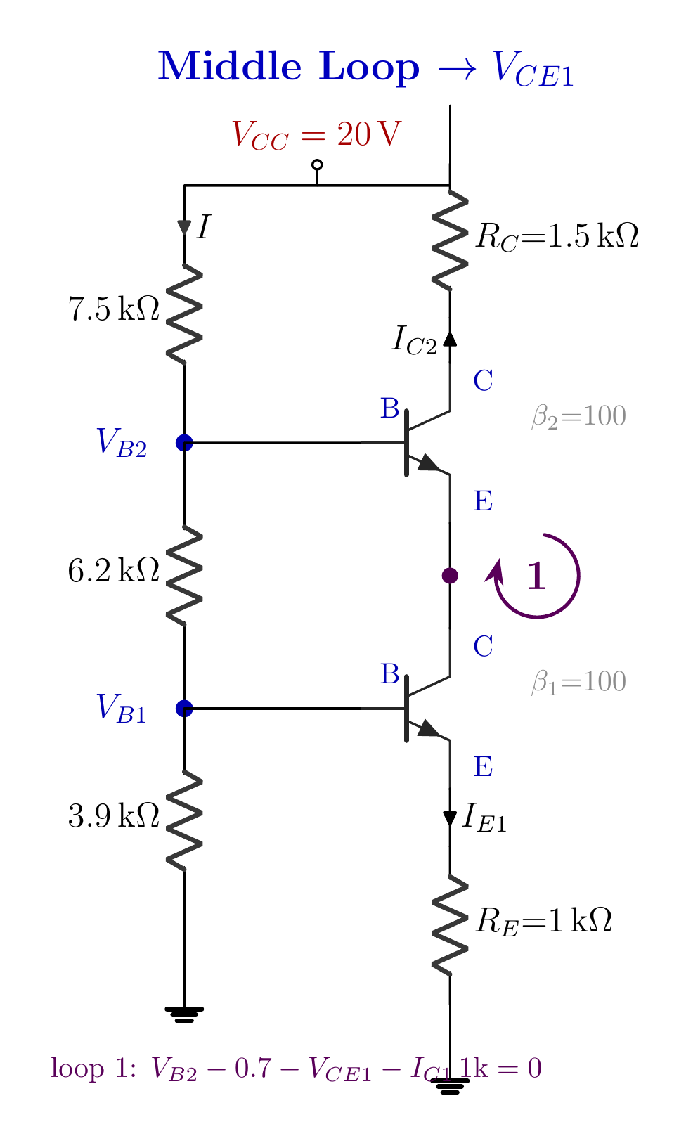
The middle loop relates V_B2, the upper V_BE, the lower V_CE1, and the R_E drop. Middle loopNarration transcript
Step three: the collector-emitter voltage of the bottom transistor. Walk the middle loop, the one marked one. Start at the upper base, 11.48 volts. Step down through the top transistor's base-emitter junction, another 0.7 drop, and you land on the node between the two transistors. That shared node is the top transistor's emitter and the bottom transistor's collector at the same time, so it sits at 11.48 minus 0.7, which is 10.78 volts. From there, the bottom transistor's collector-emitter voltage carries us down to its emitter, and the emitter sits at the current times the bottom resistor: 3.73 milliamps times 1 k is 3.73 volts. So write the whole loop in one line: 11.48 minus 0.7 minus 3.73 is 7.05 volts. V C E one is 7.05 volts. The bottom transistor drops about seven volts across itself, comfortably in its active region.
6. Upper transistor: V_CE2
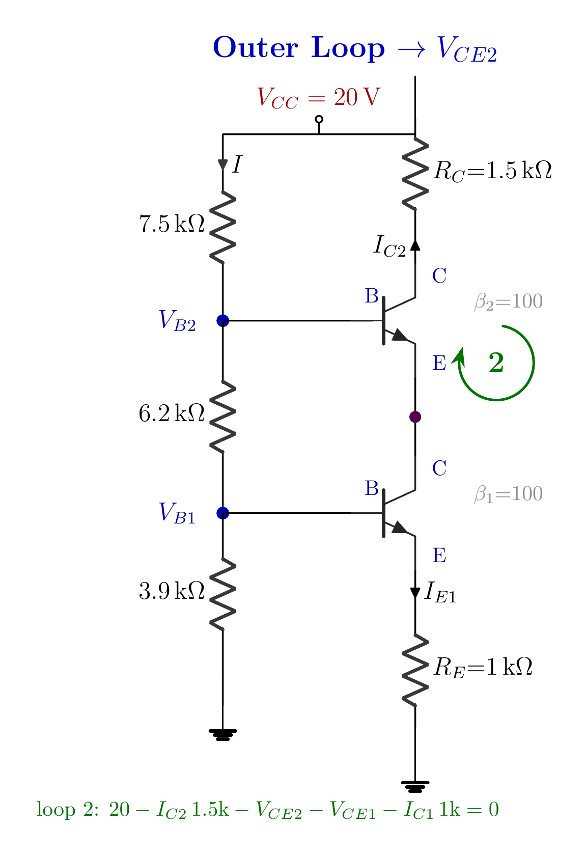
The outer loop distributes the 20 V supply across R_C, both transistors, and R_E. Outer loopVRC ≈ 3.732 mA·1.5 kΩ = 5.598 VNarration transcript
Step four, the last unknown: the collector-emitter voltage of the top transistor. Now walk the big outer loop, marked two, all the way from the supply down to ground. Start at twenty volts. First drop: across the top collector resistor, 1.5 k carrying our 3.73 milliamps, which is 5.6 volts. Next comes the top transistor itself; that drop is the V C E two we are after. Then the bottom transistor, which we just found drops 7.05 volts. And finally the emitter resistor, 1 k carrying 3.73 milliamps, another 3.73 volts. Those four drops must add back up to the twenty-volt supply. So V C E two is twenty, minus 5.6, minus 7.05, minus 3.73, which is 3.62 volts. Quick check: 5.6 plus 3.62 plus 7.05 plus 3.73 is twenty volts, exactly. Nothing leaked. All four unknowns are solved.
7. Method summary
One divider supplies two base voltages while the series transistor path carries one shared collector current. 1) Divider → VB1 and VB22) Lower base + RE → shared current3) Middle loop → VCE14) Outer loop → VCE2IC1 ≈ IC2 ≈ 3.732 mANarration transcript
Let us pocket the whole thing. Two transistors stacked on one divider looked twice as hard and turned out to be one clean pass. The three-resistor ladder gave two base voltages, 4.43 and 11.48 volts. The bottom transistor's base and emitter resistor gave the current, 3.73 milliamps, and because there is a single current path, the top transistor carries exactly the same. Then two loops finished the job: the middle loop gave 7.05 volts across the bottom transistor, the outer loop gave 3.62 volts across the top. Three ideas carry forward. One divider can bias a whole stack. Stacked transistors share one current, so you solve them together, from the bottom up. And once again, in a stiff divider beta never shows up, which is exactly why real designs build this way. We have now solved these circuits with equations. Next time we do something different: we solve a transistor graphically, by drawing a single straight line, the load line, across its characteristic curves, and reading the operating point right off the page. See you there.
Source video: Electronics Basics #19 | Two Stacked Transistors — Voltage-Divider Bias (9:34)